
Carbon beam chamfering machine

A carbon beam chamfering machine and chamfering machine technology, which are applied in the directions of grinding machine parts, machine tools suitable for grinding workpiece edges, manufacturing tools, etc.

Pending Publication Date: 2021-04-09
上海欣庆机械有限公司
View PDF0 Cites 0 Cited by
  • Summary
  • Abstract
  • Description
  • Claims
  • Application Information

AI Technical Summary

Problems solved by technology

[0004] However, most of the current chamfering equipment is suitable for glass fiber, glass, marble, wood and other materials, and the chamfering equipment suitable for carbon beams is still basically in a blank state, and people urgently need to make changes

Method used


Image

  • Carbon beam chamfering machine
  • Carbon beam chamfering machine
  • Carbon beam chamfering machine

Examples


Embodiment Construction

[0036] Specific embodiments of the present invention will be described below in conjunction with the accompanying drawings.

[0037] Herein, directional representations, such as "upper", "lower", "left", "right", "front", "rear", etc., are used to explain the structure and / or action of various parts of the disclosed embodiments, Not absolute, but relative. These representations are valid when the various parts of the disclosed embodiments are located in the positions shown in the figures, and if the position or frame of reference of the disclosed embodiments is changed, the representations are also changed according to the position or frame of reference of the disclosed embodiments. And change.

[0038] The "carbon beam" referred to in this article is the carbon fiber plate prepared to produce the predetermined length of the wind turbine blade girder. Of course, for different specifications of wind turbine blades, the predetermined length of the carbon fiber plate used to pro...


PUM


Abstract

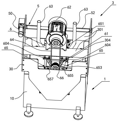
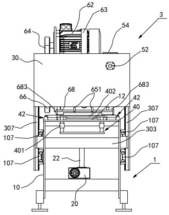
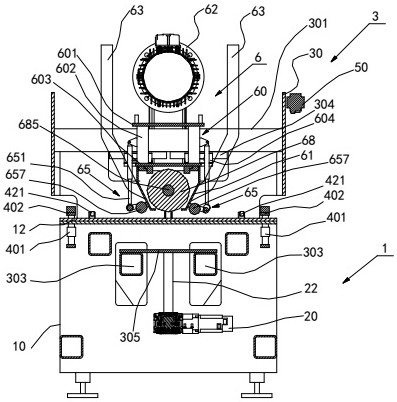
The invention relates to a carbon beam chamfering machine. The carbon beam chamfering machine comprises a base device and a grinding head device, wherein the base device comprises a frame base, an up-down driving mechanism, a carbon beam workbench and two sets of carbon beam fixing devices; the grinding head device comprises a grinding head frame, a horizontal driving mechanism and a grinding head assembly; the grinding head frame is connected with the up-down driving mechanism and can be installed on the frame base in an up-down moving manner; the grinding head assembly is connected with the horizontal driving mechanism and can be installed on the grinding head frame in a horizontal moving manner; the grinding head assembly comprises a grinding head support, a driving motor, a belt pulley and a grinding head; the grinding head support is connected to the grinding head frame in a horizontal sliding manner; the driving motor is installed on the grinding head support; the belt pulley is driven by the driving motor through belt transmission; and the grinding head is rotatably installed on the grinding head support and coaxially driven by the belt pulley. According to the carbon beam chamfering machine, a carbon beam can be ground through up-down feeding and left-right feeding of the grinding head, chamfering of the head and the tail of the carbon beam is achieved, the grinding precision is high, the efficiency is high, and the qualification rate is high.

Description

technical field [0001] The invention relates to the technical field of chamfering the front and rear ends of a blade girder plate, in particular to a carbon beam chamfering machine. Background technique [0002] In the past, the blades of wind turbines were mainly made of glass fiber materials. With the development of technology, carbon fiber materials began to be used on the blade girders due to their excellent mechanical properties and process properties. [0003] In the process of carbon beam application, various lengths of carbon fiber sheets are required according to different specifications of wind turbine blades. When making blades with carbon fiber sheets of each length specification, in order to avoid stress concentration, prevent the blades from having Wrinkles appear, and the head and tail of each carbon fiber sheet need to be chamfered. [0004] However, most of the current chamfering equipment is suitable for glass fiber, glass, marble, wood and other materia...

Claims


Application Information

Patent Timeline
Patent Type & Authority Applications(China)
IPC IPC(8): B24B9/02B24B41/06B24B47/00B24B47/16B24B47/20
CPCB24B9/02B24B41/06B24B47/00B24B47/16B24B47/20
Inventor 李生庆
Owner 上海欣庆机械有限公司
Learn More