Imaging device, control method thereof, and storage medium
A technology of an imaging device and a control method, which can be applied in the directions of image communication, TV, color TV components, etc., and can solve problems such as complex processing
- Summary
- Abstract
- Description
- Claims
- Application Information
AI Technical Summary
Problems solved by technology
Method used
Image

Examples
Embodiment 1
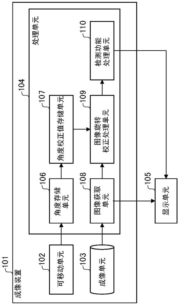
[0026] The following will refer to figure 1 Embodiment 1 of the present invention is described. figure 1 is a diagram showing the configuration of the imaging device in Embodiment 1.
[0027] The imaging device 101 includes a movable unit 102, an imaging unit 103, a processing unit 104, and the like. The display unit 105 functions as a display section for displaying images. Here, the display unit 105 may be an external monitor or the like, or may be a display unit of a terminal of a PC, and is connected to the imaging device through a network.
[0028] The processing unit 104 may also be included in a terminal such as an external PC connected to the imaging device through a network. That is, the imaging apparatus in this example is not limited to an integrated system, but includes a system configured as a single body. The display unit 105 may be integrally formed with the imaging device.
[0029] When the display unit 105 is connected to a terminal such as a PC, shooting ...
Embodiment 2
[0079] Embodiment 2 of the present invention will be described below.
[0080] The following will refer to Figure 6 Example 2 is described. Figure 6 is a diagram showing the configuration of the imaging device in Example 2. despite using figure 1 The angle storage unit 106 and the angle correction value storage unit 107 in the imaging device are shown to determine the correction angle, but in this example, the movement is performed electrically. Therefore, the method for determining the correction angle is different from that of Embodiment 1.
[0081] exist Figure 6 Among them, the imaging unit 103 is driven by the driving unit 601 to perform panning / tilting and the like driving. Here, the drive unit 601 functions as a drive section for rotating the movable unit around a movable shaft. Although the drive unit includes a motor such as a DC motor, a stepping motor, and an ultrasonic motor, and rotates the drive shaft using a gear mechanism having gears or a belt, etc., ...
Embodiment 3
[0094] Embodiment 3 of the present invention will be described below. Figure 8 is a flow chart for describing the flow of operation of Embodiment 3.
[0095] Embodiment 3 shows control in an imaging device having various types of detection / sensing functions. Examples of the sensing function include various functions such as a function for detecting a human body, a function for detecting an intruder, a function for detecting removal of an object, and the like.
[0096] Although there are various detection methods for these functions, when an object image includes movement in a rotation direction, in some cases, false detection may or may not be caused. For example, in intrusion detection or the like that issues an alarm based on a judgment as to whether an intrusion has been made to a specific area, in some cases, when an entry to the area is made and when an exit from the area is made may be caused by an image Rotation of , is reversely recognized, and intrusion detection e...
PUM
 Abstract
Description
Claims
Application Information
 - R&D Engineer
- R&D Manager
- IP Professional
- Industry Leading Data Capabilities
- Powerful AI technology
- Patent DNA Extraction
Browse by: Latest US Patents, China's latest patents, Technical Efficacy Thesaurus, Application Domain, Technology Topic.
© 2024 PatSnap. All rights reserved.Legal|Privacy policy|Modern Slavery Act Transparency Statement|Sitemap