Picture generation method and device in correction process

A technology for generating devices and screens, applied in static indicators, instruments, etc., can solve the problems of heavy system load, occupation of computing resources, and different number of LED display lights.

Active Publication Date: 2021-09-14
SHENZHEN LIDING PHOTOELECTRIC TECH
View PDF11 Cites 2 Cited by
  • Summary
  • Abstract
  • Description
  • Claims
  • Application Information

AI Technical Summary

Problems solved by technology

However, there are following defects in the above-mentioned technical solution: 1) the number of light points of each LED display screen is different, and the preset test picture needs to be adjusted frequently; 3) The upper computer software in the computer (that is, the PC terminal) has limited loading capacity, and the system will occupy most of the computing resources of the computer to

Method used


Image

  • Picture generation method and device in correction process
  • Picture generation method and device in correction process
  • Picture generation method and device in correction process

Examples


Embodiment Construction

[0054] The specific implementation manners disclosed by the present invention will be described in detail below in conjunction with the accompanying drawings. It should be understood that the specific embodiments described here are only used to illustrate and explain the present disclosure, and are not intended to limit the present disclosure.

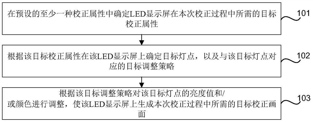
[0055] figure 1It is a flow chart of a method for generating a picture in a correction process according to an exemplary embodiment, as shown in figure 1 As shown, applied to electronic equipment, the method includes:

[0056] In step 101, a target correction attribute required by the LED display screen in this calibration process is determined from at least one preset correction attribute.

[0057] Wherein, the correction attribute includes at least one of the following: screen size correction, display area size correction, display area frame correction, frame grayscale correction, initial position correction of equally spaced point...


PUM


Abstract

The invention discloses a picture generation method and device in a correction process, which are applied to electronic equipment, and the method comprises the following steps: determining a target correction attribute required by an LED display screen in the correction process in at least one preset correction attribute; determining a target lamp point on the LED display screen according to the target correction attribute and a target adjustment strategy corresponding to the target lamp point; and adjusting the brightness value and/or the color of the target lamp point according to the target adjustment strategy, so that a target correction picture required in the correction process is generated on the LED display screen, the target correction picture is a regularity test picture composed of the lamp points on the LED display screen, and when no video signal source exists, by controlling the lamp points on the LED display screen, the testability picture required in the correction process appears on the LED display screen, video images matched with different LED display screens do not need to be manufactured in advance, the picture generation in the correction process is not influenced by the stability of the video signal source, and the correction effect is ensured.

Description

technical field [0001] The disclosure of the present invention relates to the technical field of calibration of LED display screens, and in particular to a method and device for generating images in the calibration process. Background technique [0002] At present, in the calibration process of the LED display screen, the pre-set test picture (ie, the video signal source) is presented on the computer by sending it to the PC terminal, and is transmitted to the sending device (ie, the sending card) through the signal line. The sending device (that is, the sending card) receives the test picture, and transmits the test picture (that is, the test picture) to the LED display screen with the receiving device (that is, the receiving card) for display. Finally, take a test picture on the LED display screen through the camera to finally achieve the purpose of calibration. However, there are following defects in the above-mentioned technical solution: 1) the number of light points of...

Claims


Application Information

Patent Timeline
IPC IPC(8): G09G3/32
CPCG09G3/32G09G2320/0242G09G2320/0233
Inventor 周锦志翟明
Owner SHENZHEN LIDING PHOTOELECTRIC TECH
Why Eureka
Try Eureka