A three-axis automatic screwing equipment
A screw-driving, automatic technology, used in metal processing equipment, metal processing, manufacturing tools, etc., can solve problems such as steam waste and energy waste
- Summary
- Abstract
- Description
- Claims
- Application Information
AI Technical Summary
Problems solved by technology
Method used
Image
Examples
Embodiment 1
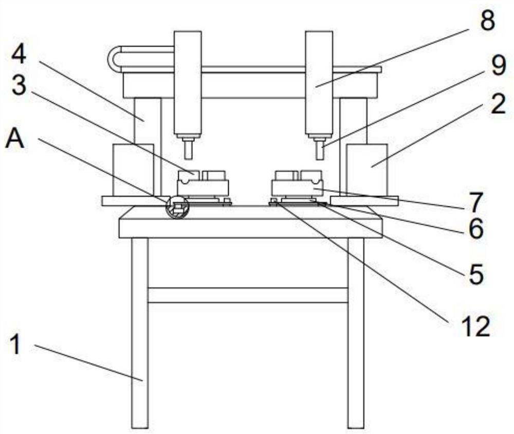
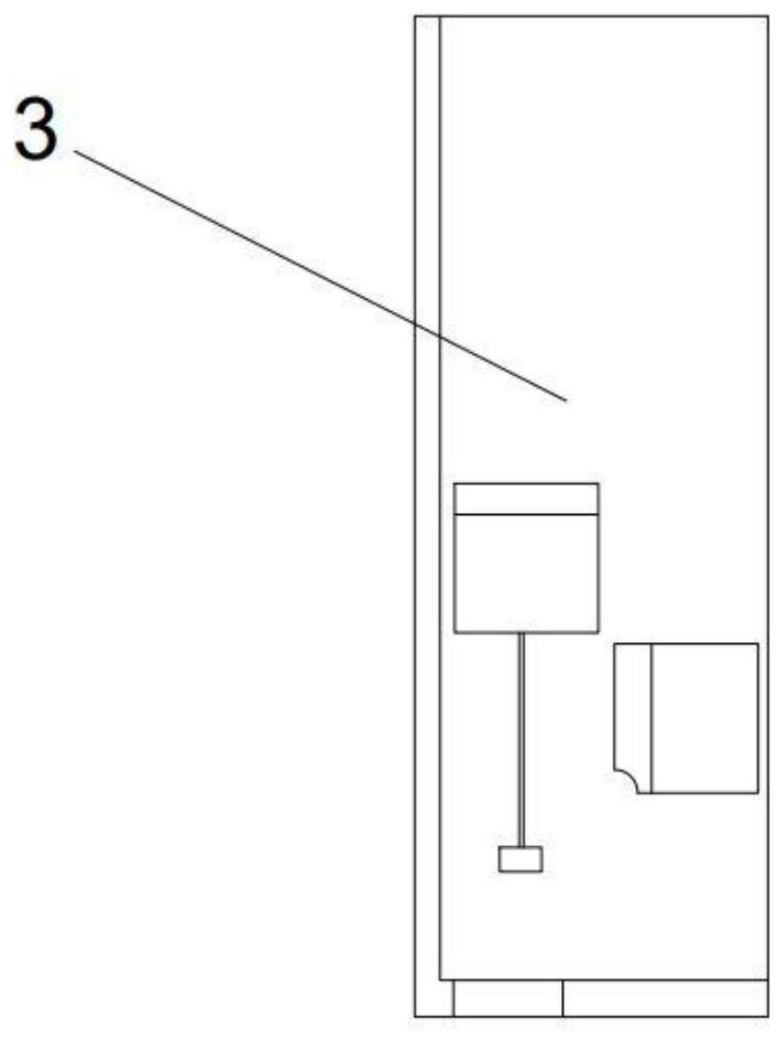
[0032] Such as figure 1 , figure 2 Shown, the technical scheme that the present invention takes is as follows:
[0033] The invention discloses a three-axis automatic screwing device, comprising: a base 1, a pair of screw automatic feeding mechanisms 2, a pair of clamping and positioning mechanisms 3 and a fixing frame 4; a pair of said screw automatic feeding mechanisms are symmetrically Arranged on both sides of the base; a pair of clamping and positioning mechanisms are arranged between a pair of said screw automatic feeding mechanisms; the clamping and positioning mechanism includes a horizontal bottom plate 5, and the horizontal bottom plate is equipped with a Y-axis Rail 6, one side of the Y-axis slide rail is also equipped with an X-axis slide rail 7, and the X-axis slide rail is equipped with two clamping devices perpendicular to each other; the fixed frame is installed on the outside of the base, and the fixed A pair of Z-axis cylinders 8 are housed on the frame, a...
Embodiment 2
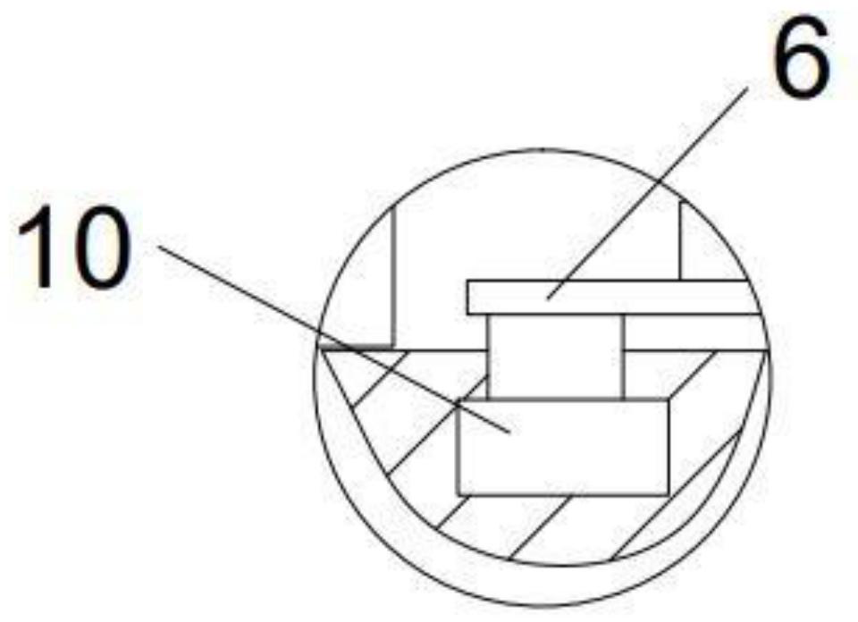
[0035] Such as image 3 As shown, the difference between the present embodiment 2 and the implementation 1 is that the base is equipped with eight lifting motors 10, and the eight lifting motors are divided into two groups on average, and each group of four lifting motors is respectively located on the four corners of the horizontal base plate. The output shaft is used to lift the horizontal base plate.
[0036] The three-axis automatic screwing device also includes a control unit 11, which is used to send an alarm to personnel and manually adjust the rise and fall of the output shaft of the lifting motor or directly control the rise and fall of the output shaft of the lifting motor.
[0037] The control unit of this embodiment can adopt a computer system and a PLC (Programmable Logic Controller).
[0038]When this embodiment is implemented, the control unit is used to send an alarm to personnel and manually adjust the rise and fall of the output shaft of the lift motor or di...
Embodiment 3
[0040] Such as Figure 4 , Figure 5 , Figure 6 The difference between the present embodiment 3 and the implementation 2 is that a level adjustment device 12 is installed on the top of the horizontal bottom plate, and the level adjustment device includes a cylinder 13, a transparent and non-conductive liquid is housed in the cylinder, and the cylinder The middle part is equipped with a glass cover 14, and the lower surface of the center of the glass cover is equipped with a circular conductive coil 15, and one of the conductive coils is connected to the positive pole of the power supply through a conductive wire; an air bag 16 is floating on the transparent non-conductive liquid. The top of the airbag is equipped with a conductive shaped frame 17, and the side wall of the airbag is provided with an arc-shaped conductive shaped side panel 18, and the bottom of the conductive shaped side panel is connected with a flexible conductive wire 20, and the conductive wire is electric...
PUM
 Abstract
Description
Claims
Application Information
 - R&D
- Intellectual Property
- Life Sciences
- Materials
- Tech Scout
- Unparalleled Data Quality
- Higher Quality Content
- 60% Fewer Hallucinations
Browse by: Latest US Patents, China's latest patents, Technical Efficacy Thesaurus, Application Domain, Technology Topic, Popular Technical Reports.
© 2025 PatSnap. All rights reserved.Legal|Privacy policy|Modern Slavery Act Transparency Statement|Sitemap|About US| Contact US: help@patsnap.com


