
Transfer device

A transfer device and transfer technology, which is applied in the directions of lifting device, storage device, transportation and packaging, etc., can solve the problem of easy to enlarge invalid space and so on.

Pending Publication Date: 2021-11-05
DAIFUKU CO LTD
View PDF14 Cites 0 Cited by
  • Summary
  • Abstract
  • Description
  • Claims
  • Application Information

AI Technical Summary

Problems solved by technology

As a result, in the technology described in Patent Document 1, the ineffective space for storing articles (20) in the automatic warehouse (10) tends to become large, and there is room for improvement in order to improve storage efficiency.

Method used


Image

  • Transfer device
  • Transfer device
  • Transfer device

Examples


Embodiment Construction

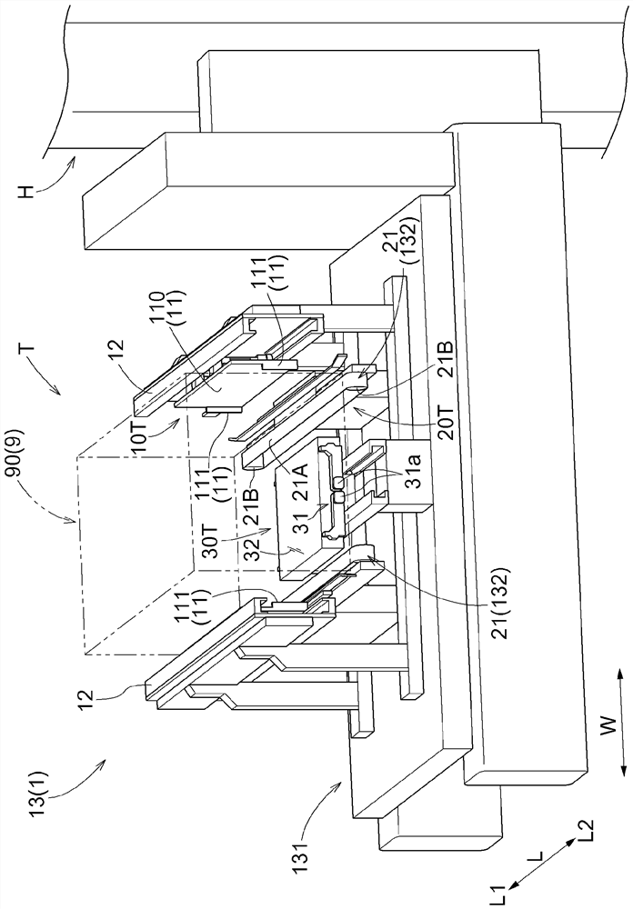
[0021] A transfer device according to this embodiment will be described with reference to the drawings. For example figure 1 and figure 2 As shown, the transfer device 13 is applied to the article transfer device 1 for transferring a target article 90 to be transferred (transferred) in an article storage facility 100 that accommodates a plurality of articles 9 .

[0022] 〔Schematic structure of the article storage facility〕

[0023] First, a schematic configuration of the article storage facility 100 will be described.

[0024] Such as figure 1 and figure 2 As shown, the article storage device 100 has an article transfer device 1 for transferring articles 9 and an article storage rack 2 for accommodating a plurality of articles 9 . In the illustrated example, a pair of article storage racks 2 are provided with one article conveyance device 1 interposed therebetween.

[0025] The article storage rack 2 includes a plurality of storage portions A. As shown in FIG. Each o...


PUM


Abstract

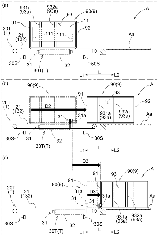
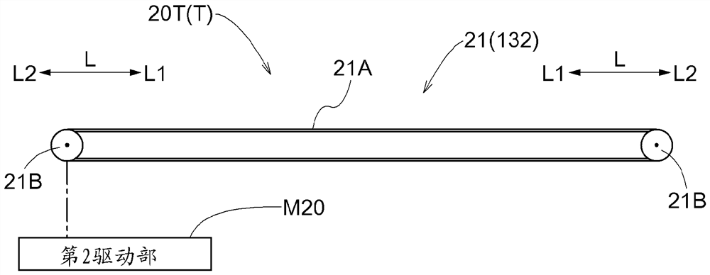
This transfer device comprises a load unit (132) on which an object (90) is loaded, and a transport unit (T) to transfer the object (90) between an accommodation unit (A) and the load unit (132), wherein: the transfer unit (T) comprises a first transfer device (10T) that holds the object (90) and moves the object (90) in a depth direction (L), and a second transport device (20T) that moves the portion of the object (90) loaded on the load unit (132) in the depth direction (L); a first transfer distance (D1), which is the distance the object (90) is moved by the first transfer device (10T), is less than the total transfer distance, which is the distance the object (90) is moved in the depth direction (L) between the load unit (132) and the accommodation unit (A); and the transfer unit (T) uses the second transfer device (20T) to move the object (90) the distance that the first transfer distance (D1) is short of the total transfer distance.

Description

technical field [0001] The present invention relates to a transfer device for transferring a target article between a storage unit for storing the article. Background technique [0002] An example of such a transfer device is disclosed in Japanese Unexamined Patent Publication No. 2004-203528 (Patent Document 1). Hereinafter, the reference numerals in parentheses in the description of the background art are the reference numerals of Patent Document 1. FIG. [0003] In the technique described in Patent Document 1, articles (discharging) are carried out between a plurality of storage parts (15) provided in an automatic warehouse (10) by means of a cargo transfer device (30) equipped with a stacker crane (12). 20) Transfer. The cargo transfer device (30) includes a pair of side arms (advancing and retreating mechanism 71) that hold the article (20) from both sides in the width direction and advance and retreat toward the storage portion (15). The load transfer device (30) is...

Claims


Application Information

Patent Timeline
IPC IPC(8): B65G1/04
CPCB66F9/07B66F9/141B65G1/0435B66F9/12B65G1/0407B25J13/085B66F9/183
Inventor 藤田孝塚本邦博江本旭
Owner DAIFUKU CO LTD
Learn More