Millimeter wave antenna

A millimeter wave antenna and horn antenna technology, applied in the field of antenna equipment, can solve problems such as adverse effects of antenna radiation performance, unfavorable antenna expansion, unfavorable expansion, etc., and achieve the effects of high engineering application value, expanding antenna bandwidth, and reducing processing difficulty.

Pending Publication Date: 2021-11-23
ANHUI UNIVERSITY
View PDF0 Cites 0 Cited by
  • Summary
  • Abstract
  • Description
  • Claims
  • Application Information

AI Technical Summary

Problems solved by technology

Traditional millimeter-wave antennas based on PCB (printed circuit board) technology mostly adopt the form of series-fed patch antennas. This antenna has the advantages of simple structure, low cost, and easy processing, but it is not conducive to expansion and forms a phased array antenna. In the form of series feed, the transceiver chip and the antenna are located on the same side, which is not condu

Method used


Image

  • Millimeter wave antenna
  • Millimeter wave antenna
  • Millimeter wave antenna

Examples


Embodiment

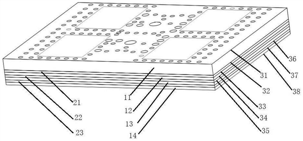
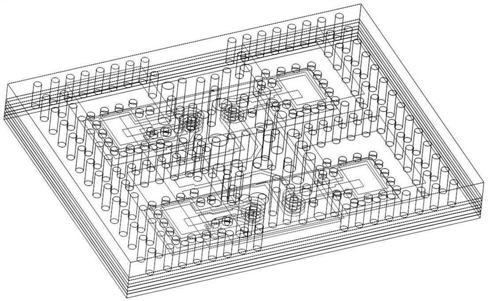
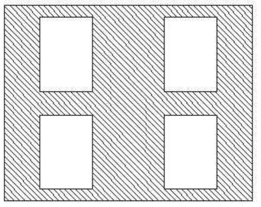
[0062] A millimeter-wave antenna working at 77-81GHz is provided here. It includes 4 layers of Rogers3003 microstrip boards with a thickness of 0.127mm. 0.1mm prepreg is used for bonding. The antenna includes 4 antenna units, the size of the antenna is 10mm in length and 7.6mm in width, and the distance between the centers of the horn cavity of the antenna unit is 5mm on the long side and 3.8mm on the wide side. The 4-layer microstrip board corresponds to 8 copper clad layers. Looking from top to bottom, the pattern of each copper clad layer is as follows: Figure 3 to Figure 9 shown. Correspondingly, in order to shield and isolate the antenna unit and provide continuous grounding between the upper and lower layers, 6 different types of metallized holes are set up. The minimum diameter of the metallized holes is 0.2mm, and the positions of the metallized holes are as follows: Figure 10 ~ Figure 15 shown.

[0063] The first metallized via hole, the second metallized via hol...


PUM


Abstract

A millimeter wave antenna disclosed by the present invention comprises four layers of printed circuit boards and three layers of prepreg layers. The printed circuit boards and the prepreg layers are alternately stacked, the upper and lower end faces of the printed circuit boards are both provided with copper-clad layers, and the top of the millimeter wave antenna is provided with a plurality of rectangular horn antenna units arranged in rectangular grids. A rectangular quasi coaxial feed-coaxial feed-band ground coplanar waveguide feed three-stage feed structure is adopted, a feed line is led out to the back surface of the millimeter wave antenna, and various metallized through holes are formed in the millimeter wave antenna; the invention provides a semi-open two-stage rectangular horn antenna structure based on four layers of PCBs, and adopts a rectangular quasi coaxial feed-coaxial feed-band ground coplanar waveguide feed GCPW three-stage feed structure to realize antenna back feed.

Description

technical field [0001] The present invention relates to the technical field of antenna equipment, in particular to a millimeter wave antenna. Background technique [0002] With the development of millimeter-wave technology, the demand for millimeter-wave antennas in engineering applications is becoming more and more strong. Low-cost, scalable, and high-performance millimeter-wave antennas are the development direction of millimeter-wave antennas. Traditional millimeter-wave antennas based on PCB (printed circuit board) technology mostly adopt the form of series-fed patch antennas. This antenna has the advantages of simple structure, low cost, and easy processing, but it is not conducive to expansion and forms a phased array antenna. In the form of series feed, the transceiver chip and the antenna are located on the same surface, which is not conducive to the expansion of the antenna, and the series feed line and chip also have an adverse effect on the radiation performance o...

Claims


Application Information

Patent Timeline
IPC IPC(8): H01Q1/38H01Q1/50
CPCH01Q1/38H01Q1/50
Inventor 陈谦陈见
Owner ANHUI UNIVERSITY
Why Eureka
Try Eureka