Supercharge Your Innovation With Domain-Expert AI Agents!

Display module

A technology for display modules and display panels, which is applied to instruments, identification devices, etc., and can solve problems such as display panel wrinkles and cracks

Active Publication Date: 2021-11-30
WUHAN CHINA STAR OPTOELECTRONICS SEMICON DISPLAY TECH CO LTD
View PDF5 Cites 5 Cited by
  • Summary
  • Abstract
  • Description
  • Claims
  • Application Information

AI Technical Summary

Problems solved by technology

[0004] The embodiment of the present application provides a display module, which can reduce the technical problem that the part of the display panel located in the terminal area of ​​the display module in the current technology is prone to wrinkles and cracks during the bending process.

Method used


Image

  • Display module
  • Display module

Examples


Embodiment 1

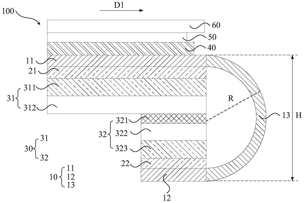
[0030] Such as figure 1 shown, for figure 1 It is a schematic structural diagram of the display module 100 provided in the first embodiment of the present application; wherein, the display module 100 includes a display panel 10 and a support structure 30, and the display panel 10 includes a first plane part 11 and a second plane part 12 and a bent portion 13 located between the first planar portion 11 and the second planar portion 12, the second planar portion 12 is bent to the side away from the light emitting direction of the display panel 10, so The support structure 30 is located between the first plane part 11 and the second plane part 12, the support structure 30 includes a first support part 31 close to the first plane part 11 and a first support part 31 close to the second plane The second supporting part 32 of the part 12;

[0031] Wherein, the rigidity of the second support portion 32 is greater than the rigidity of the first support portion 31 .

[0032] In the e...

Embodiment 2

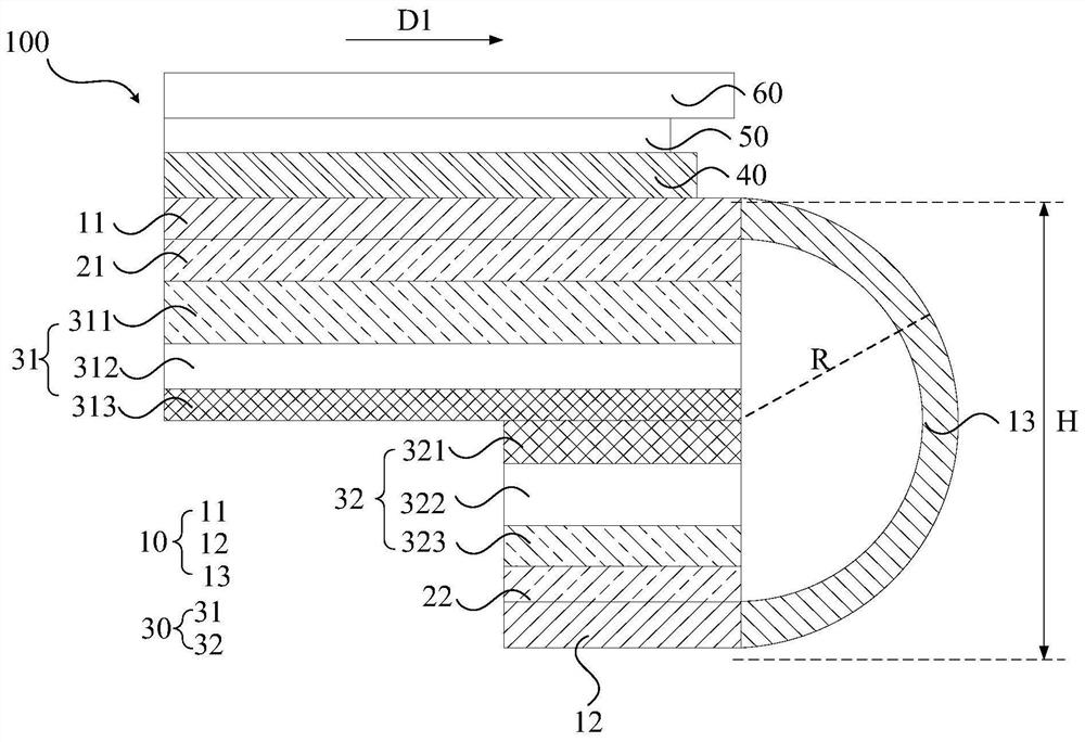
[0052] Such as figure 2 As shown, it is a schematic structural diagram of the display module 100 provided in the second embodiment of the present application; wherein, the structure of the display module 100 in the second embodiment of the present application is the same or similar to the structure of the display module 100 in the first embodiment of the present application , the only difference is that the first support portion 31 includes a first buffer layer 311 , a first metal layer 312 and a second reinforcement plate 313 , and the first buffer layer 311 is disposed away from the first planar portion 11 The first metal layer 312 is arranged on the side of the first buffer layer 311 away from the first planar part 11, and the second reinforcing plate 313 is arranged on the first metal layer 311. The side of the layer 312 away from the first buffer layer 311 ; wherein, the first buffer layer 311 , the first metal layer 312 and the second reinforcing plate 313 are integrall...


PUM


Abstract

The embodiment of the invention provides a display module. The invention discloses a display module. The display module comprises a display panel and a supporting structure, wherein the display panel comprises a first plane part, a second plane part and a bending part located between the first plane part and the second plane part, wherein the second plane part is bent towards the side away from a light emitting direction of the display panel, and the supporting structure is located between the first plane part and the second plane part; the supporting structure comprises a first supporting part close to the first plane part and a second supporting part close to the second plane part, and rigidity of the second supporting part is larger than that of the first supporting part; the first supporting part is arranged on a back face of the first plane part, the second supporting part is arranged on the back face in the second plane part, and rigidity of the second supporting part is larger than that of the first supporting part, so stiffness of the second plane part is enhanced; the risk that the terminals located on the second plane portion are prone to wrinkling and cracking in the bending process of the display module is reduced, and bending resistance of the display module is further improved.

Description

technical field [0001] This application relates to the field of display, in particular to a display module. Background technique [0002] As a display component of electronic equipment, display modules have been widely used in various electronic products, and the narrow frame and flexible and foldable designs are increasingly favored by terminal manufacturers and consumers. The implementation of the narrow bezel solution mainly depends on the bending of the binding area so that the driver chip is bent to the back of the display module. In the existing display module, the display panel includes a display area and a binding area located on one side of the display area. In the display area, a foam structure and a reinforcing plate are generally attached to the back of the display panel. The foam structure acts as a buffer. The reinforcing plate plays a role of fixing, and only the back plate is provided in the part corresponding to the terminal in the binding area. During the...

Claims


Application Information

Patent Timeline
IPC IPC(8): G09F9/30
CPCG09F9/301
Inventor 黄威
Owner WUHAN CHINA STAR OPTOELECTRONICS SEMICON DISPLAY TECH CO LTD
Features
  • R&D
  • Intellectual Property
  • Life Sciences
  • Materials
  • Tech Scout
  • Unparalleled Data Quality
  • Higher Quality Content
  • 60% Fewer Hallucinations
Learn More