Clamp capable of fixing and adjusting multiple optical lenses

A technology of optical lenses and fixtures, which is applied in the direction of optics, optical components, optical surface grinders, etc., can solve the problems of low work efficiency, inability to adjust angles from multiple angles, and inconvenient processing by operators, so as to improve work efficiency and stability , Improve the effect of machining accuracy

Active Publication Date: 2022-01-11
上饶市舜达光电有限公司
View PDF8 Cites 0 Cited by
  • Summary
  • Abstract
  • Description
  • Claims
  • Application Information

AI Technical Summary

Problems solved by technology

[0006] In order to overcome the disadvantages of the above-mentioned patent that the angle cannot be adjusted from multiple angles after the lens is clamped, it is not convenient for the operator to process, and a large number of lenses cannot be clamped at one time, and the work efficiency is low, the technical problem to be solved by the present invention is to provide a The lens can be adjusted at multiple angles, which is convenient for the operator to process and has high work efficiency. The fixture that can fix and adjust a large number of optical lenses

Method used


Image

  • Clamp capable of fixing and adjusting multiple optical lenses
  • Clamp capable of fixing and adjusting multiple optical lenses
  • Clamp capable of fixing and adjusting multiple optical lenses

Examples


Embodiment 1

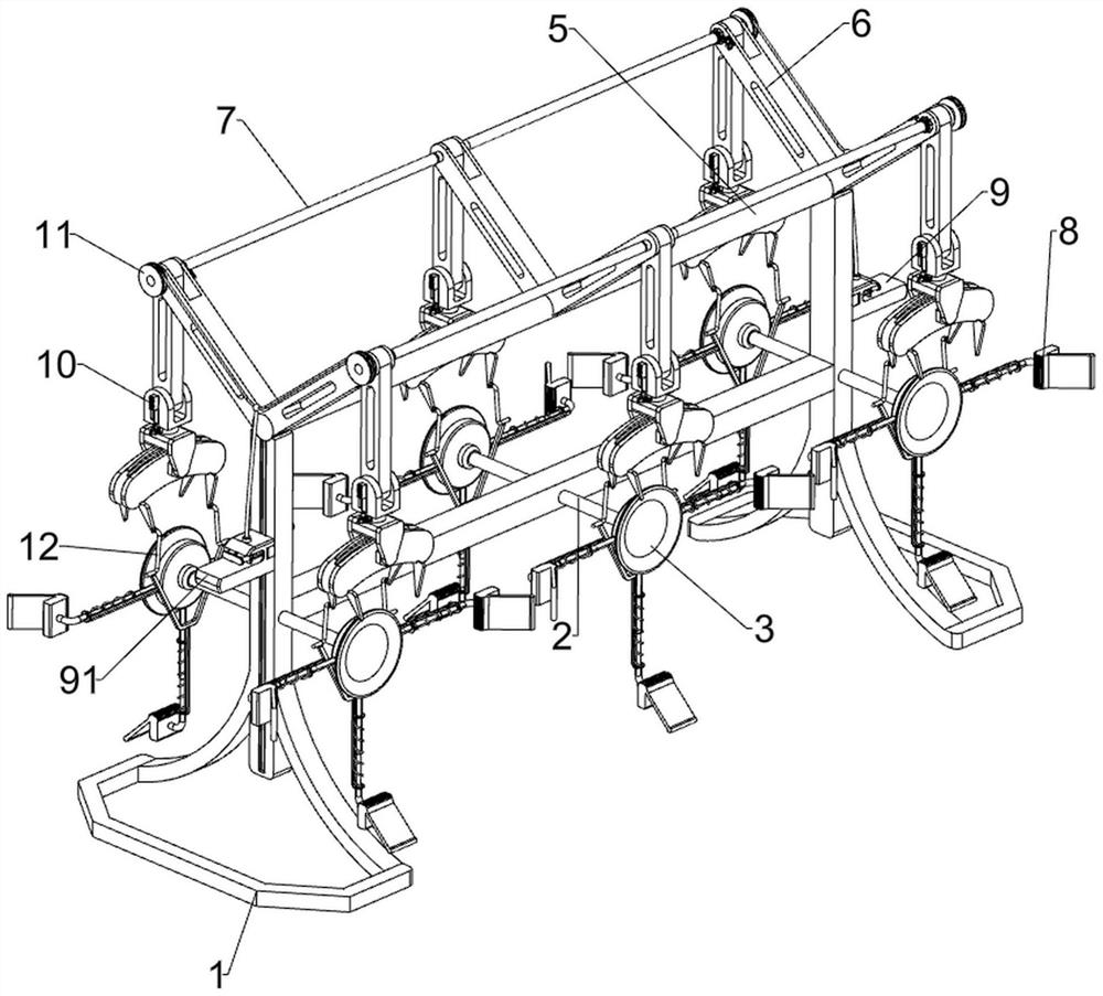
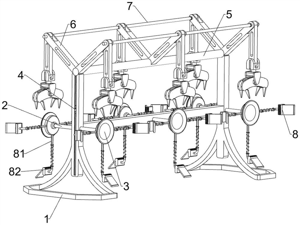
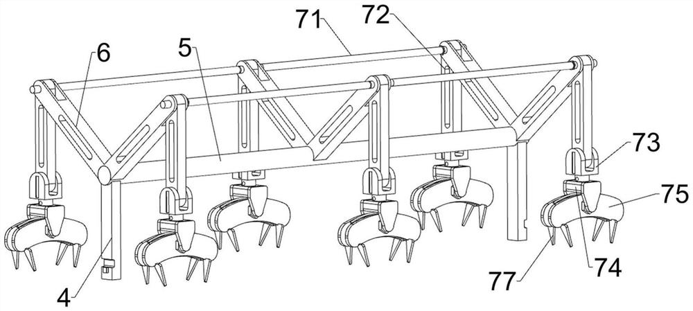
[0035] A fixture that can fix and adjust a large number of optical lenses, such as Figure 1-5 As shown, it includes a mounting frame 1, a fixed rod 2 and a suction cup 3. The middle part of the mounting frame 1 is connected with three fixed rods 2 evenly spaced from left to right, and the fixed rods 2 run through the mounting frame 1. Both ends are connected with a suction cup 3 for fixing the lens through a threaded connection, and also include a lifting rod 4, a cross bar 5, a V-shaped frame 6, a clamping component 7 and a positioning component 8, and the left and right sides of the mounting frame 1 are There is a chute, and the lifting rod 4 is slidably connected in the chute, and the tops of the lifting rods 4 on both sides are connected with a cross bar 5 by welding, and three V-shaped joints are welded on the cross bar 5 evenly Frame 6, a clamping assembly 7 that can clamp the lens is installed between the three V-shaped frames 6, and a positioning assembly 8 for positi...

Embodiment 2

[0040] On the basis of Example 1, such as figure 1 , Figure 6 , Figure 7 , Figure 8 and Figure 9 As shown, it also includes a limit mechanism 9, the limit mechanism 9 includes a lifting block 91, a guide frame 92, a limit block 93, a return spring 94 and a guide block 96, and the left and right sides of the mounting frame 1 are all slidably connected with Two guide blocks 96, the two guide blocks 96 are symmetrical up and down, the guide block 96 on the top is connected with the elevating rod 4 by welding, the left and right sides of the installation frame 1 have openings, the guide blocks 96 run through the opening, and the bottom The guide block 96 of the guide block 96 is connected with a lifting block 91 by welding, and the upper part of the lifting block 91 is slidably connected with a guide frame 92. The position block 93, the stop block 93 and the lift block 91 are connected with a return spring 94, the return spring 94 is sleeved on the outside of the guide fra...

Embodiment 3

[0045] On the basis of Example 2, such as figure 1 , Figure 10 , Figure 11 and Figure 12 As shown, a pulling mechanism 11 is also included, and the pulling mechanism 11 includes a winding wheel 111, a first backguy 112, a second backguy 113, a ratchet 114, a guide sleeve 115, a ratchet 116, a fourth spring 117 and a shifting block 118, Both left and right ends of the first connecting rod 71 are connected with reels 111, and there are second stay wires 113 wound between the two reels 111 on the left and between the two reels 111 on the right. The middle part of the second backguy 113 and the top of the lifting block 91 are connected with the first backguy 112 by means of lap connection, and the leftmost and rightmost V-shaped frames 6 are connected with guide sleeves 115, which slide on the guide sleeves 115. A ratchet 116 is connected in a conventional manner, and a fourth spring 117 is connected between the ratchet 116 and the guide sleeve 115. The fourth spring 117 is ...


PUM


Abstract

The invention relates to a clamp, in particular to a clamp capable of fixing and adjusting multiple optical lenses. According to the clamp capable of fixing and adjusting the multiple optical lenses, multi-angle adjustment can be conducted on the lenses, machining of operators is facilitated, and the working efficiency is high. In order to solve the technical problem, the invention provides the clamp capable of fixing and adjusting the multiple optical lenses, which comprises a mounting frame and the like. A plurality of fixing rods are evenly connected to the middle of the mounting frame at intervals from left to right, suction cups used for fixing the lenses are connected to the front ends and the rear ends of the plurality of fixing rods, lifting rods, a cross rod, V-shaped frames, clamping assemblies and positioning assemblies are further included, and the lifting rods are slidably connected to the left side and the right side of the mounting frame. The lenses can be clamped through the clamping assemblies, multi-angle clamping can be conducted on the clamped lenses, and the accurate grinding procedure, the polishing procedure, the cleaning procedure or the trimming procedure can be conveniently conducted on the lenses.

Description

technical field [0001] The invention relates to a fixture, in particular to a fixture capable of fixing and adjusting a large number of optical lenses. Background technique [0002] Optical lenses are lenses made of optical glass. Optical glass has specific requirements for optical properties such as refractive index, dispersion, transmittance, spectral transmittance and light absorption. Optical lenses are usually used as glasses lenses after processing. Clamps are usually required to fix the lens. [0003] After retrieval, the patent publication number is: the patent of CN210499611U, discloses a kind of fixture strength adjustable device of optical lens, comprises workbench, and the top of described workbench is fixedly connected with rubber pad, support block and fixing seat, and described rubber The top of the pad is movably connected with a lens, the top of the support block is fixedly connected with a first clamping block, the right side of the fixed seat is fixedly c...

Claims


Application Information

Patent Timeline
Patent Type & Authority Applications(China)
IPC IPC(8): B24B13/005B24B41/06
CPCB24B13/0055B24B9/146Y02P40/57
Inventor 俞伟华
Owner 上饶市舜达光电有限公司
Why Eureka
Try Eureka