Assembling equipment for USB connector joint processing and production

A technology for assembling equipment and connectors, which is applied in the direction of assembly/disassembly of contacts, which can solve problems such as inability to limit the housing and terminals, and achieve the effect of avoiding falling apart

Inactive Publication Date: 2022-01-21
深圳市连亿达科技有限公司
View PDF0 Cites 4 Cited by
  • Summary
  • Abstract
  • Description
  • Claims
  • Application Information

AI Technical Summary

Problems solved by technology

[0005] Aiming at the deficiencies of the prior art, the present invention provides an assembly equipment for the processing and production of USB connector joints that can be loaded and unloaded by itself, and can limit the housing and terminals, so as to overcome the need for manual loading and unloading of existing equipment , and the disadvantage of being unable to limit the housing and terminals

Method used


Image

  • Assembling equipment for USB connector joint processing and production
  • Assembling equipment for USB connector joint processing and production
  • Assembling equipment for USB connector joint processing and production

Examples


Embodiment 1

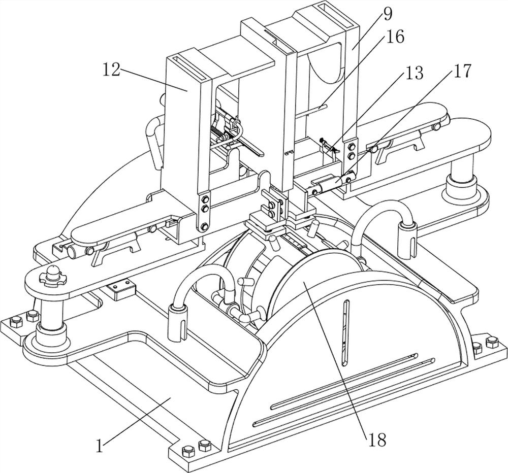
[0093] Such as figure 1 , figure 2 , image 3 , Figure 4 , Figure 5 , Image 6 , Figure 7 with Figure 8 The shown assembly equipment for processing and producing USB connector joints includes a collection frame 1, a first fixing plate 3, a contact switch 4, a first fixing column 5, a first electric push rod 6, a first push plate 7, The limit frame 8, the first shell blanking frame 9, the second fixed plate 10, the terminal blanking frame 11, the second shell blanking frame 12, the limit mechanism 13 and the collection mechanism 14, and the top of the collection frame 1 is welded with two The first fixed plate 3, the first fixed plate 3 is symmetrically arranged left and right, the left side of the first fixed plate 3 top left side is provided with a contact switch 4, and the first fixed column 5 is welded on the top of the two first fixed plates 3, The first electric push rods 6 are installed inside the two first fixed columns 5 through bolts, and the first push pl...

Embodiment 2

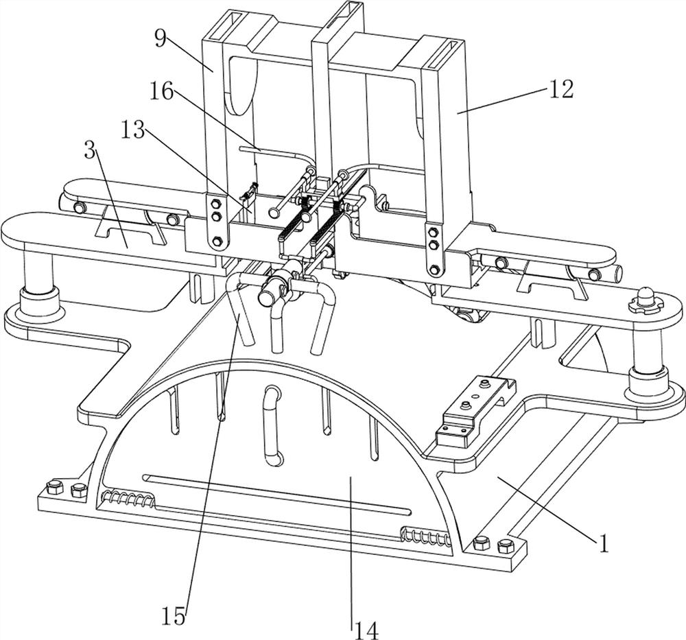
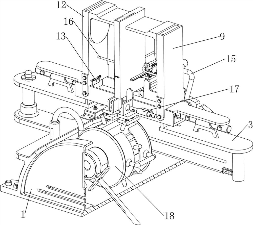
[0098] On the basis of Example 1, such as figure 1 , figure 2 , image 3 , Figure 9 , Figure 10 , Figure 11 , Figure 12 , Figure 13 , Figure 14 , Figure 15 , Figure 16 , Figure 17 with Figure 18 As shown, a pusher mechanism 15 is also included, and the pusher mechanism 15 includes a second fixed column 151, a second electric push rod 152, a second limit plate 153, a push column 154, a pressure sensor 155 and a pressure rod 156, collecting The frame 1 top rear side is welded with the second fixed column 151, and the second fixed column 151 top is provided with the second electric push rod 152, and the second electric push rod 152 telescoping rod front side is provided with the second limit plate 153, and the second limit plate 153 is arranged on the second limit plate. The top of the positioning plate 153 is in contact with the bottom of the terminal blanking frame 11, and the lower side of the rear part of the second limiting plate 153 is provided with a ...


PUM


Abstract

The invention relates to assembling equipment, in particular to assembling equipment for USB connector joint processing and production. The invention provides the assembling equipment for processing and producing the USB connector joint, which can be used for automatically loading and unloading and can be used for limiting the shell and the terminal. The assembling equipment comprises a collecting frame, first fixing plates, wherein the top of the collecting frame is connected with the two first fixing plates; a contact switch arranged on the left side of the top of the first fixing plate on the left side; and first fixing columns, wherein the tops of the two first fixing plates are connected with the two first fixing columns. A second electric push rod telescopic rod drives a second limiting plate and a push column to move forwards, so that the second limiting plate blocks other terminals, meanwhile, the push column moves forwards, an assembled USB connector joint is pushed into a collection frame, and in this way, people do not need to manually return the installed USB connector joint.

Description

technical field [0001] The invention relates to an assembly device, in particular to an assembly device for processing and producing USB connector joints. Background technique [0002] USB connectors are widely used due to the advantages of fast plugging and unplugging. During the production and processing of USB connectors, USB connectors need to be assembled. At present, the assembly process of USB connectors is generally manual work, and the number of operators is large. , it is necessary to manually assemble the shell of the USB connector joint with the terminals, which is labor-intensive and inefficient. [0003] The existing USB connector assembly machine includes a collection frame, a first fixing plate, a first fixing column and a limit frame, and it is necessary to manually place the shell and terminals of the USB connector joint in the limit frame, and then the assembly machine Squeeze the shell and terminals of the USB connector joints to complete the assembly, a...

Claims


Application Information

Patent Timeline
Patent Type & Authority Applications(China)
IPC IPC(8): H01R43/20
CPCH01R43/20
Inventor 黄成东黄成金
Owner 深圳市连亿达科技有限公司
Why Eureka
Try Eureka