Process for unloading catalyst from petrochemical equipment

A technology of petrochemical devices and catalysts, which is applied in chemical instruments and methods, methods for chemically changing substances by using atmospheric pressure, and the petroleum industry, and can solve problems that may endanger the health of workers

Inactive Publication Date: 2004-03-03
JIANGSU TIANPENG PETROCHEMICAL TECH CO LTD
View PDF0 Cites 0 Cited by
  • Summary
  • Abstract
  • Description
  • Claims
  • Application Information

AI Technical Summary

Problems solved by technology

This catalyst dust contains carcinogens (Ni 3 S 2 ), will endanger the health of workers

Method used


Image

  • Process for unloading catalyst from petrochemical equipment
  • Process for unloading catalyst from petrochemical equipment
  • Process for unloading catalyst from petrochemical equipment

Examples


Embodiment 1

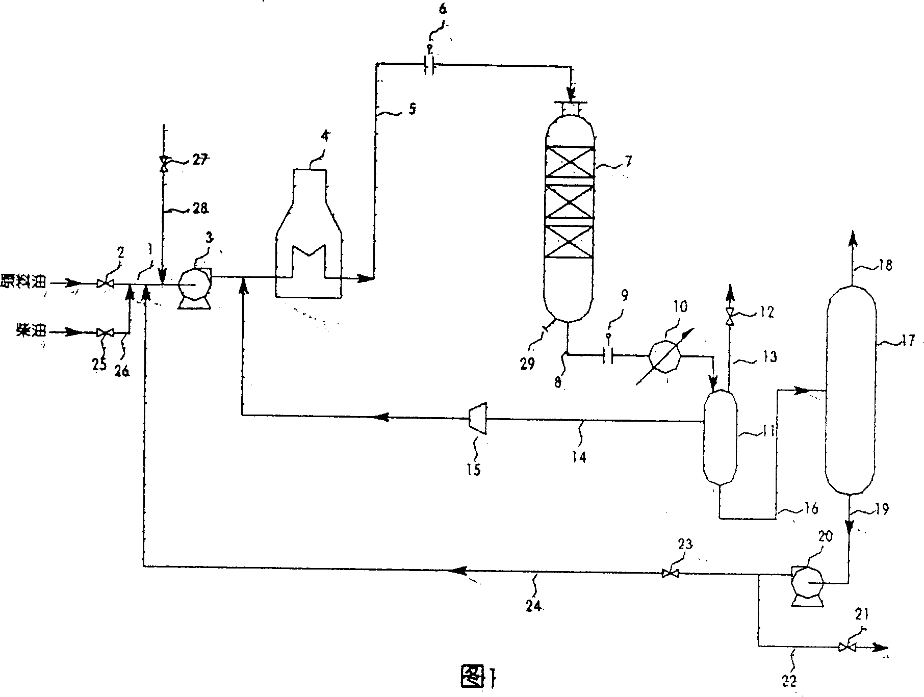
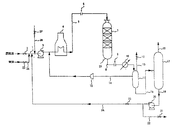
[0018] Fig. 1 is a schematic diagram of the film-forming method on the surface of an oil agent circulation catalyst. There are valves 2 and pumps 3 on the raw oil pipeline 1 . At the outlet of the pump, there is a heating furnace 4. The heating furnace 4 and the reaction tower 7 are connected by a pipeline 5, and there is a flange 6 on the pipeline, which can be inserted into a blind plate. The reaction tower 7 is connected with the cooler 10 and the gas-liquid separator 11 through the pipeline 8, and there is a flange 9 on the pipeline 8, which can be inserted into a blind plate. The top of the gas-liquid separator 11 is connected with the valve 12 through the pipeline 13, so that the tail gas is discharged to other equipment. The hydrogen in the gas-liquid separator 11 is pressurized by the gas compressor 15 and sent to the heating furnace 4 through the pipeline 14 . The liquid in the gas-liquid separator 11 is sent to a distillation column 17 through a line 16 . The top...

Embodiment 2

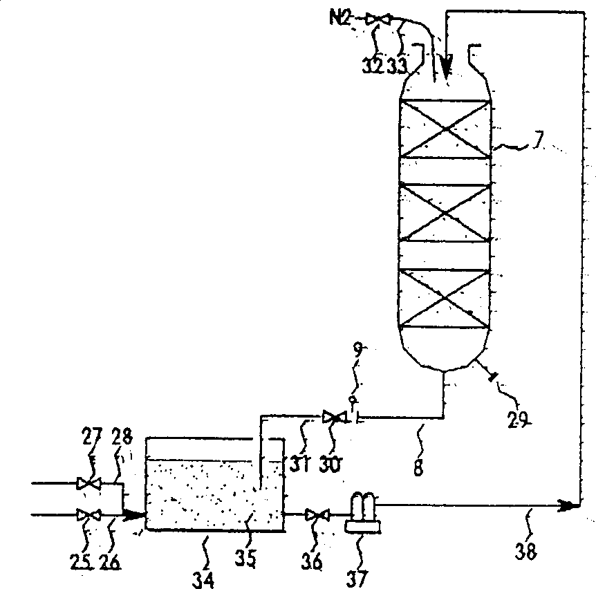
[0021] figure 2 It is a schematic diagram of the film-forming method on the catalyst surface soaked in oil. Open valve 25 and lead solvent oil and fuel oil into storage tank 34 through pipeline 26. Open the valve 27 and inject the film-forming agent into the solvent oil in the storage tank 34 through the pipeline 28, and prepare the oil agent 35 in advance. Solvents and film formers are simply stirred at room temperature.

[0022] After the device is stopped according to the general shutdown procedure, a valve 30 is installed at the flange 9 in the pipeline 8 at the bottom of the reaction tower 7, and the pipeline 31 is connected to the storage tank 34. Open the valve 36, and the oil agent 35 is pressed into the reaction tower 7 through the pipeline 38 with the pump 37 until the oil agent immerses the catalyst in the tower. In order to prevent air from entering the reaction tower, while injecting the oil agent 35 into the reaction tower, open the valve 32 and flush nitrogen...


PUM


Abstract

A process for unloading catalyst from petrochemical equipment features that before the catalyst is unloaded, it is immersed in oil phase compared from solvent and filming agent for 4-10 hr or cyclically contacted with said oil phase for 10-30 hr to generate a layer of film on the surface of catalyst, resulting in no generation of ash dust.

Description

1. Technical field [0001] The method of the invention is applicable to the unloading of various reaction tower catalysts in petrochemical devices, especially the unloading method of hydrocracking reaction towers. 2. Background technology [0002] Various catalysts are used in the reaction towers of petrochemical plants. After the catalysts have been used for a period of time, the catalysts in the reaction towers must be unloaded because their activity decreases or the equipment needs to be overhauled. However, the catalyst in the reaction tower, especially the catalyst in the hydrocracking reaction tower has a strong redox property. When in contact with air, an oxidative exothermic reaction will occur, causing the catalyst to generate heat and spontaneously ignite. [0003] For small reaction towers, before unloading, air and steam are introduced into the reaction tower to burn and regenerate the catalyst (in-situ regeneration), and then remove the catalyst. However, in-pl...

Claims


Application Information

Patent Timeline
Patent Type & Authority Patents(China)
IPC IPC(8): B01J3/02C10G47/00
Inventor 曹放许桂清
Owner JIANGSU TIANPENG PETROCHEMICAL TECH CO LTD
Why Eureka
Try Eureka