

Detection device with automatic shape correction function for PE pipe production
A detection device and automatic technology, applied in the direction of measuring devices, instruments, etc., can solve the problems of inability to correct the shape of the concave part, waste of PE pipe resources, and low practicability of the detection device, so as to speed up the correction speed, improve the quality of correction, and improve the practicality. sexual effect
- Summary
- Abstract
- Description
- Claims
- Application Information
AI Technical Summary
Problems solved by technology
Method used
Image

Examples
Embodiment 1
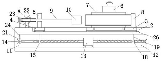
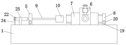
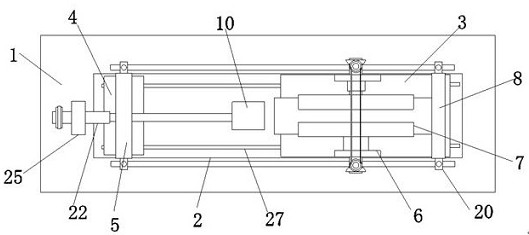
[0033] Embodiment one, by Figure 1 to Figure 7 Given, the present invention comprises console 1, and the top of console 1 is provided with groove 2, and the interior of groove 2 is provided with support plate one 3 and support plate two 4, and support plate one 3 is positioned at one of support plate two 4. side, the middle position of the top of the support plate two 4 is provided with a fixed column 5, and the two sides of the top of the support plate one 3 are symmetrically provided with support columns 6, and the two support columns 6 are provided with a clamping plate 7 on the side close to each other. The clamping plates 7 are connected by a moving mechanism, and the top of the support plate 3 is provided with a stop plate 8 on one side of the two clamping plates 7, and the stop plate 8 and the fixed column 5 are connected by a distance adjustment mechanism 12 , through the design of the spacing adjustment mechanism 12, it is convenient to realize the relative movement ...
Embodiment 2
[0036] Embodiment two, on the basis of embodiment one, by figure 1 , figure 2 , image 3 and Figure 4 Given, the pulling member includes an engaging rod 19 and an engaging seat 20, the tops of the first slider 15 and the second slider 17 are provided with an engaging rod 19, and both sides of the stop plate 8 and the fixed column 5 are symmetrically provided with an engaging seat 20 , the connecting rod 19 is fixedly connected with the connecting seat 20, the top of the console 1 is provided with a slot communicating with the receiving groove 11, and one end of the connecting rod 19 runs through the inside of the slot, the support plate one 3 and the support plate two 4 Both sides of the bottom end of the groove are symmetrically provided with moving blocks 26, and the inner bottom of the groove 2 is provided with a moving groove 27 which is slidably connected with the moving block 26;
[0037] When slider one 15 and slider two 17 move relative to each other, it will driv...
Embodiment 3
[0038] Embodiment three, on the basis of embodiment one, by figure 1 , figure 2 , image 3 , Figure 4 and Figure 6 Given, the transmission group includes transmission parts and connecting parts, the transmission parts include connecting cylinder 22, pulley two 23, belt one 24 and fixing seat 25, one end of connecting rod 9 is provided with connecting cylinder 22 outside, and the top of console 1 is installed There is a fixed seat 25, and the connecting cylinder 22 runs through the fixed seat 25. One of the screw rods 14 is provided with a pulley 1 21, and one end of the connecting cylinder 22 is provided with a pulley 2 23, and the belt pulley 21 and the pulley 2 23 pass through Belt one 24 is connected, the connecting rod 9 and the connecting cylinder 22 are connected through an adapter, and the connecting piece includes a block 28, a slot 29 and a bearing 30, and the connecting cylinder 22 and the fixing seat 25 are connected through a bearing 30, and the connecting ro...
PUM
 Abstract
Description
Claims
Application Information