
Guiding method and system for crossing visual target point based on specified course of unmanned aerial vehicle

A technology for drones and target points, which is applied in the field of drone navigation and can solve problems such as no solution.

Pending Publication Date: 2022-03-22
NAVAL AERONAUTICAL UNIV
View PDF0 Cites 0 Cited by
  • Summary
  • Abstract
  • Description
  • Claims
  • Application Information

AI Technical Summary

Problems solved by technology

[0003] At present, there are more and more applications of UAVs based on visual tasks. Sometimes it is necessary for UAVs to plan the trajectory based on the visual target point, such as flying over the visual target point with a specified course, but there is no related solution.

Method used


Image

  • Guiding method and system for crossing visual target point based on specified course of unmanned aerial vehicle
  • Guiding method and system for crossing visual target point based on specified course of unmanned aerial vehicle
  • Guiding method and system for crossing visual target point based on specified course of unmanned aerial vehicle

Examples


Embodiment 1

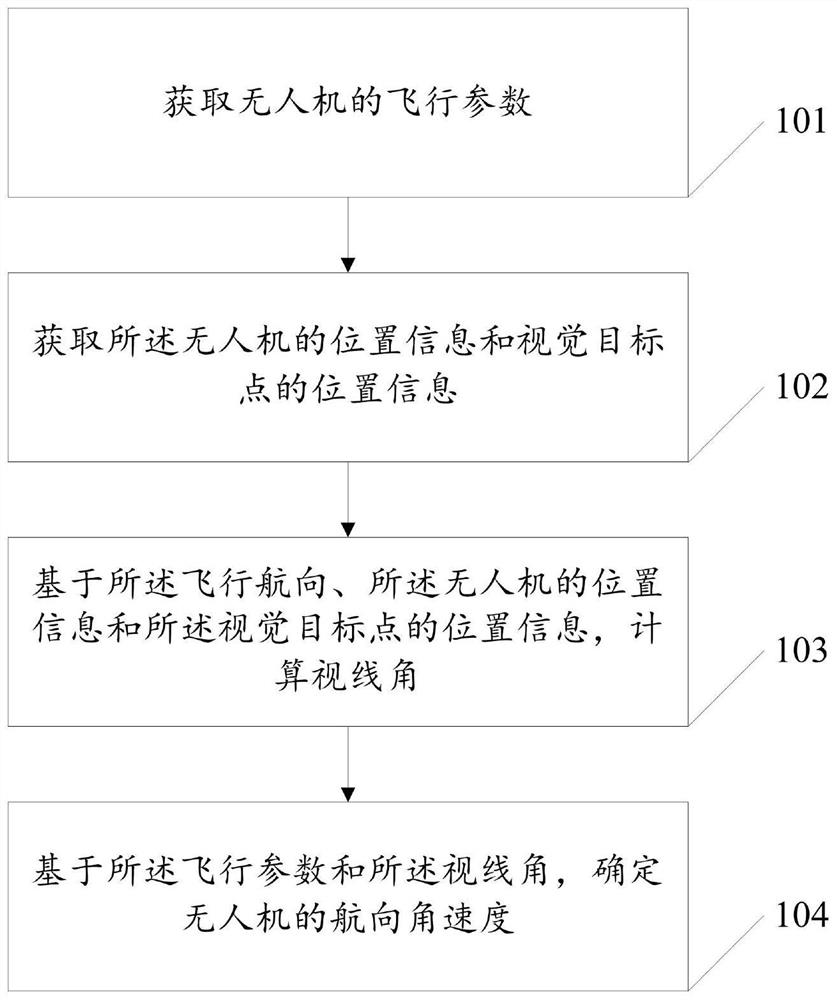
[0046] see figure 1 , this embodiment provides a guidance method based on the specified course of the UAV passing through the visual target point, which can solve the problem that the UAV flies over the visual target point with the specified course, including:

[0047] Step 101: Obtain flight parameters of the drone; the flight parameters include flight speed, flight heading and specified heading.

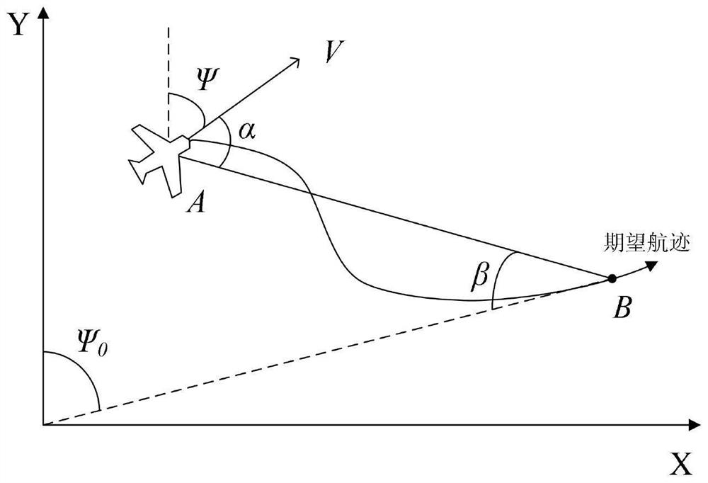
[0048] An example is: the flight speed of the UAV is V, and the flight course is based on the north direction, clockwise from 0 to 360°, denoted as Ψ; the specified course is the direction of the visual target point that the UAV flight track requires, denoted as Ψ 0 .

[0049] Step 102: Obtain the position information of the drone and the position information of the visual target point.

[0050] An example is: the current position A of the drone and the current position B of the visual target point are obtained in real time by the onboard sensor carried by the drone.

[0051] S...

Embodiment 2

[0072] This embodiment provides a guidance system based on the designated course of the UAV to pass through the visual target point, such as Figure 4 shown, including:

[0073] The flight parameter acquisition module 401 is used to acquire the flight parameters of the drone; the flight parameters include flight speed, flight heading and specified heading.

[0074] The position information obtaining module 402 is configured to obtain the position information of the drone and the position information of the visual target point.

[0075] A line of sight angle calculation module 403, configured to calculate a line of sight angle based on the flight heading, the position information of the drone, and the position information of the visual target point.

[0076] The heading angular velocity calculation module 404 is configured to determine the heading angular velocity of the UAV based on the flight parameters and the line-of-sight angle; the heading angular velocity is used to pas...


PUM


Abstract

The invention discloses a guiding method and system for crossing a visual target point based on a specified course of an unmanned aerial vehicle, and relates to the technical field of unmanned aerial vehicle navigation, and the method comprises the steps: obtaining flight parameters of the unmanned aerial vehicle; the flight parameters comprise a flight speed, a flight course and a specified course; acquiring position information of the unmanned aerial vehicle and position information of a visual target point; calculating a sight angle based on the flight course, the position information of the unmanned aerial vehicle and the position information of the visual target point; determining the course angular velocity of the unmanned aerial vehicle based on the flight parameters and the line-of-sight angle; the course angular velocity is used for enabling the unmanned aerial vehicle to pass through a visual target point in a specified course. The purpose that the unmanned aerial vehicle passes through the visual target point in the specified course can be achieved.

Description

technical field [0001] The invention relates to the field of unmanned aerial vehicle navigation technology, in particular to a guidance method and system for passing through a visual target point based on a designated course of an unmanned aerial vehicle. Background technique [0002] In recent years, with the rapid development of sensor technology, micro-electromechanical technology, wireless communication technology and aviation technology, UAV technology is becoming more and more mature. At present, UAVs can complete many special tasks by carrying different equipment, and have very broad military and civilian prospects. Whether the drone can complete the task safely and smoothly depends largely on the navigation and control capabilities of the drone. Although the current research on the navigation and control of the drone is relatively mature, there are still many problems that need to be overcome in practical applications. . [0003] At present, there are more and more...

Claims


Application Information

Patent Timeline
IPC IPC(8): G05D1/10
CPCG05D1/101
Inventor 祁亚辉陈麒杰刘玄冰闫实王超吴修振刘伟肖支才尹高扬
Owner NAVAL AERONAUTICAL UNIV
Learn More