A Sparse Array Optimal Configuration Method for Reducing Beamforming Sidelobes in Range Dimension

A sparse array and optimized configuration technology, applied in antenna array, design optimization/simulation, constraint-based CAD, etc., can solve the problems of distance-dimensional beam sidelobe elevation and sidelobe interference, etc., and achieve the reduction of distance-dimensional digital beamforming side lobe effect

Active Publication Date: 2022-05-13
ROCKET FORCE UNIV OF ENG
View PDF6 Cites 0 Cited by
  • Summary
  • Abstract
  • Description
  • Claims
  • Application Information

AI Technical Summary

Problems solved by technology

However, due to the sparse distribution of array elements, the sidelobe of the range dimension beam will be raised, and the sidelobe interference will be introduced.

Method used


Image

  • A Sparse Array Optimal Configuration Method for Reducing Beamforming Sidelobes in Range Dimension
  • A Sparse Array Optimal Configuration Method for Reducing Beamforming Sidelobes in Range Dimension
  • A Sparse Array Optimal Configuration Method for Reducing Beamforming Sidelobes in Range Dimension

Examples


Embodiment 1

[0086] In order to prove the feasibility and effectiveness of the method of the present invention, an embodiment of the present invention is given below. This embodiment is implemented on the premise of the method of the present invention, and detailed implementation is provided, but protection of the present invention The scope is not limited to this example.

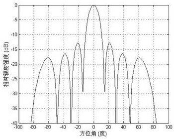
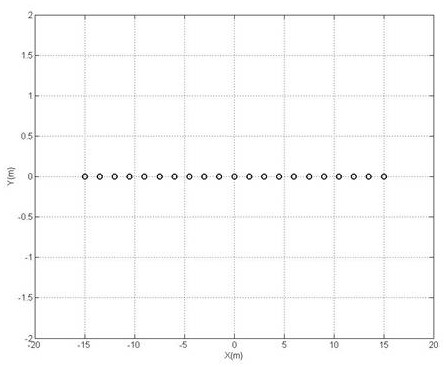
[0087] Consider a sparse array with 21 array elements distributed in a 30m caliber, optimize the array configuration of the array elements according to the method of the present invention, the specific steps are as follows:

[0088] Step 1, take the zero point of the X-axis coordinate as the reference point, and the X coordinate of the array element relative to the reference point x n Indicates the position of the array element, and the distribution form shown in (12) is selected as the basic formation of the sparsely distributed antenna array;

[0089] Step 2, select the center array element as the reference array e...


PUM


Abstract

The invention discloses a sparse array optimal configuration method for reducing the distance-dimensional beamforming sidelobe: step 1, according to the caliber distributed by the sparsely distributed antenna array D and number of elements N , the non-uniform array form of odd elements is the basic formation of the distributed sparse array; Step 2, select the central array element of the sparsely distributed antenna array as the reference array element; Step 3, calculate the basis for adjusting the distance between the array elements required by the basic formation Quantity: Step 4, calculate the X coordinates of each array element relative to the reference array element; Step 5, calculate the phase weighting matrix composed of phase weighting vectors; Step 6, calculate the distance dimension beam pattern with the distance r as a variable; Step 7, pair Random perturbation is set for the meta position; step 8, calculate a new beam pattern. Under the condition of no amplitude weighting, the present invention realizes the effect of digital beamforming in the distance dimension with lower sidelobes only by optimizing the position of the array elements, thereby reducing the influence of interference signals entering from the sidelobes in the distance dimension.

Description

technical field [0001] The invention belongs to sensor array optimization array formation and digital beamforming technology in the field of array signal processing, and relates to a sparse array optimization configuration method for reducing distance-dimension beamforming sidelobes. A technology that realizes digital beamforming and reduces sidelobes in the distance dimension, specifically a sparse array optimal configuration method that reduces beamforming sidelobes in the distance dimension. Background technique [0002] Traditional antenna arrays usually adopt a concentrated array arrangement. In order to avoid grating lobes or high side lobes, the array element spacing should usually meet d ≤ lambda / 2, where lambda Indicates the signal wavelength. When the array aperture D distance from radiation source R Satisfy the far field condition R> 2 D 2 / lambda , it can be approximately considered that the incident wave of the radiation source is a parallel wave. ...

Claims


Application Information

Patent Timeline
Patent Type & Authority Patents(China)
IPC IPC(8): G06F30/20G06F30/18H01Q21/00H01Q21/29G06F111/04
CPCG06F30/20G06F30/18H01Q21/0087H01Q21/29G06F2111/04
Inventor 胡昌华李智钟都都唐勇肖开清杨剑何川方晓夏巍巍
Owner ROCKET FORCE UNIV OF ENG
Why Eureka
Try Eureka