

Floating cutter handle for reaming and using method of floating cutter handle
A tool handle and reaming technology, which is applied in the direction of reamers, reaming devices, metal processing equipment, etc., can solve the problems of large radial runout of reamers, low life of reamers, poor surface quality, etc., and achieve stable production efficiency, The effect of good processing quality and low tool cost
- Summary
- Abstract
- Description
- Claims
- Application Information
AI Technical Summary
Problems solved by technology
Method used
Image

Examples
Embodiment Construction
[0033] The present invention will be further described in detail below in combination with specific embodiments and with reference to the accompanying drawings. It should be emphasized that the following description is only exemplary and not intended to limit the scope of the invention and its application.
[0034] Non-limiting and non-exclusive embodiments will be described with reference to the following drawings, wherein like reference numerals refer to like parts unless specifically stated otherwise.
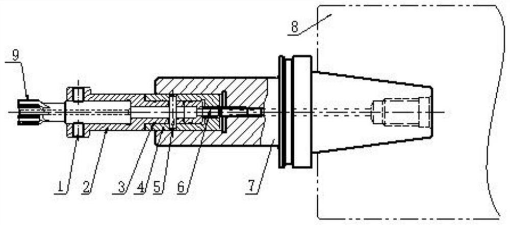
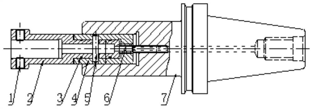
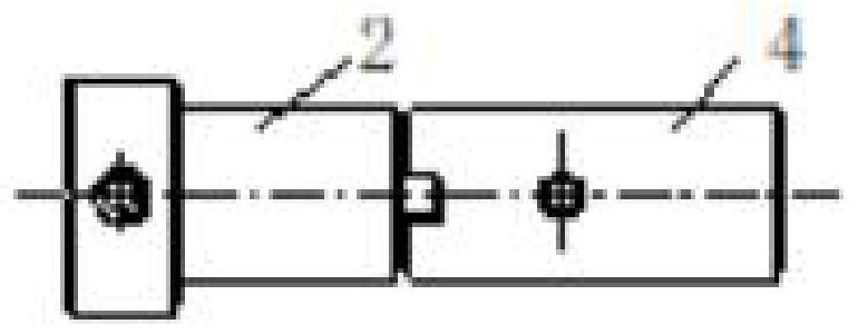
[0035] Such as figure 1 A floating tool holder for reaming shown in ~ includes a floating device and a tool handle 7. The tool handle 7 is a conventional standard tool holder, which can generally be a hydraulic tool holder, a side-fixed tool holder, a shrink-fit tool holder, etc. , the floating device is installed on the left part of the handle 7 and rotates synchronously with the handle 7. The floating device includes a tool socket 2, a handle socket 4, and a connecting pi...
PUM
 Abstract
Description
Claims
Application Information