
Constant-force grinding system integrating detection with grinding

A detection system and grinding technology, which can be applied to the parts of grinding machine tools, grinding drive devices, grinding/polishing equipment, etc., can solve the problems of increased grinding force, burns on grinding surfaces, and high labor intensity of workers. , to achieve the effect of improving production efficiency, improving processing quality and expanding grinding range

Active Publication Date: 2016-11-09
FOSHAN POLYTECHNIC
View PDF7 Cites 0 Cited by
  • Summary
  • Abstract
  • Description
  • Claims
  • Application Information

AI Technical Summary

Problems solved by technology

[0004] In general, the feeding system of CNC grinding machine is to feed with constant displacement according to the speed given in the program. During the feeding process, the grinding force changes due to the change of the back cutting amount, so that the deformation of the machine tool drive chain is at unstable state
When grinding cemented carbide discs, diamond grinding wheels are used to grind cemented carbide materials. The constant displacement feed of the machine tool feed mechanism causes a sharp increase in grinding force, which generates a large amount of grinding heat, which can easily cause the cemented carbide materials to grinding surface burn
Therefore, the grinding of the end face of the cemented carbide disc can only be processed by manual feeding with an ordinary grinder. The disadvantages of this processing method are: high labor intensity, low production efficiency, small and unstable feed force

Method used


Image

  • Constant-force grinding system integrating detection with grinding
  • Constant-force grinding system integrating detection with grinding
  • Constant-force grinding system integrating detection with grinding

Examples


Embodiment Construction

[0031] In order to facilitate those skilled in the art to better understand the essence of the present invention, the specific embodiments of the present invention will be described in detail below with reference to the accompanying drawings.

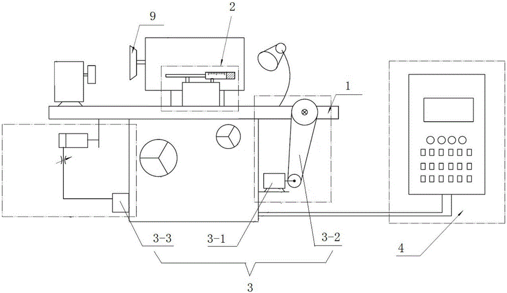
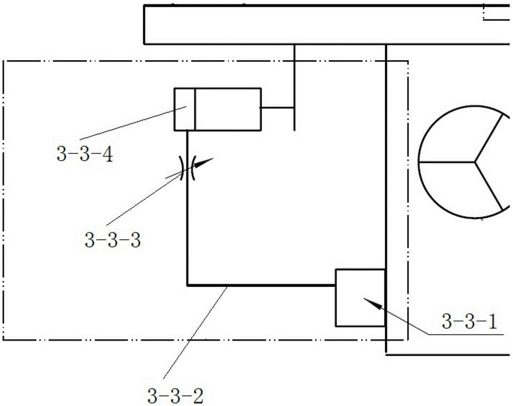
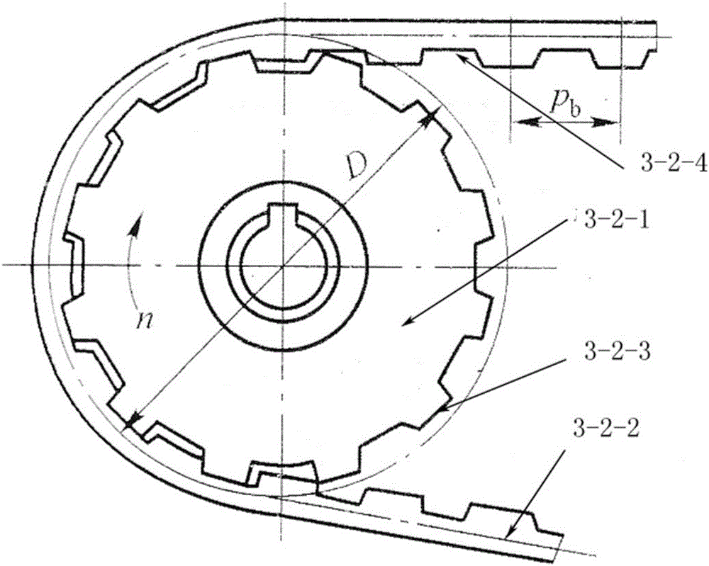
[0032] Such as figure 1 , figure 2 As shown, a constant force grinding system integrating detection and grinding functions includes: a workbench 1, an online inspection system installed on the workbench 1, a constant force grinding system 3, and a controller 4. The controller 4 controls the constant force grinding system 3 to work according to the information fed back from the online detection system 2. The constant force grinding system 3 is composed of a servo motor 3-1, a synchronous transmission mechanism 3-2, and a worktable retracting device 3. -3 composition, the servo motor 3-1 is a constant torque servo motor, the constant torque servo motor is converted into a constant feed force of the worktable 1 through a synchronous transmiss...


PUM


Abstract

The invention discloses a constant-force grinding system integrating detection with grinding. The constant-force grinding system is characterized by comprising a working table, as well as an on-line detecting system, a constant-force grinding system and a controller mounted on the working table; the controller controls operation of the constant-force grinding system according to the information fed back by the on-line detecting system; the constant-force grinding system comprises a servo motor, a synchronous transmission mechanism and a working table return device; the servo motor serves as a constant-torque servo motor; the constant-torque servo motor is converted into the constant feed force of the working table through transmission of the synchronous transmission mechanism; and the working table return device is used for realizing returning of horizontal operation of the working table. Aiming at a machine tool transmission chain deformation phenomenon caused by unstable grinding feed force during ground finish and the constant-displacement forceful feeding mode adopted in numerically controlled grinder design, the design concept of constant-force grinding is adopted, and the grinding feed force is set into a constant quantity from an unstable variable, so that deformation of a machine tool transmission chain is in a stale state.

Description

Technical field [0001] The invention relates to the technical field of hard alloy disc grinding, in particular to a constant force grinding system integrating detection and grinding functions. Background technique [0002] All machines are composed of three parts: the prime mover, the transmission mechanism and the actuator. The overall layout of the machinery includes the distribution of motion and power, the design of the transmission system, and the working conditions of the actuator. The driving mechanism can be composed of electric motors, hydraulic mechanisms, wind mechanisms, etc. It provides power and movement for the entire mechanical device, and is the heart of the mechanical device; the function of the transmission mechanism is to transmit movement and power, and it combines the power of the driving mechanism with the original The motion is transmitted to the actuator, and the nature, direction, size and speed of the original motion mechanism can be changed through th...

Claims


Application Information

Patent Timeline
IPC IPC(8): B24B51/00B24B47/20B24B49/04
CPCB24B47/20B24B49/04B24B51/00
Inventor 张涛川段春梅杨伟李大成
Owner FOSHAN POLYTECHNIC
Learn More