Pole fastening mechanism and assembly line

A technology for fastening mechanisms and fastening devices, which can be used in workpiece clamping devices, metal processing equipment, metal processing, etc., and can solve time-consuming problems

Inactive Publication Date: 2022-06-24
安徽新高电气有限公司
1 Cites 0 Cited by

AI-Extracted Technical Summary

Problems solved by technology

[0004] In the prior art including the above-mentioned patents, after the transfer of the pole and the assembly is completed, the screw sucked by the pneumatic torque wrench system is tightened at this time, and then the assembly is realized, but the existing screw fastening device is passed The screw tap is reciprocally rotated to fasten the screw. In the installation process of the pole, there are generally at least two poles. For example, three screwdrivers are the most common. If one screwdriver is used for pos...

Method used

[0070] The driving gear 2.6 and the telescopic shaft assembly 2.61 are surrounded by a plurality of arc-shaped rods 2,65, so as to prevent the driving gear 2.6 from beating teeth when shifting gears.
[0092] The pole assembly mechanism provided by the pre...

Abstract

The invention discloses a pole fastening mechanism and an assembly line, and relates to the field of pole processing, the pole fastening mechanism comprises a rack, and a plurality of screwdrivers are slidably arranged on the rack; the connecting rod assembly is arranged on the rack; all the screwdrivers are connected to the connecting rod assembly; the horizontal distance between the screwdrivers can be adjusted through stretching and retracting of the connecting rod assembly. According to the pole fastening mechanism, the horizontal distance between the screwdrivers is adjusted through the connecting rod assembly, so that the screwdrivers are adjusted, and then the pole fastening mechanism is used for tightening poles on assembly parts of different specifications.

Application Domain

Work holdersMetal working apparatus

Technology Topic

EngineeringAssembly line +2

Image

  • Pole fastening mechanism and assembly line
  • Pole fastening mechanism and assembly line
  • Pole fastening mechanism and assembly line

Examples

  • Experimental program(1)

Example Embodiment

[0044] In order to enable those skilled in the art to better understand the technical solutions of the present invention, the present invention will be further described in detail below in conjunction with the accompanying drawings.
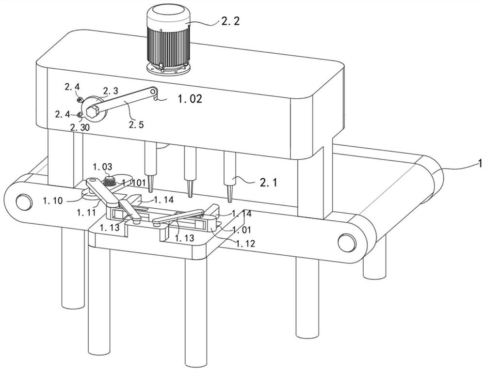
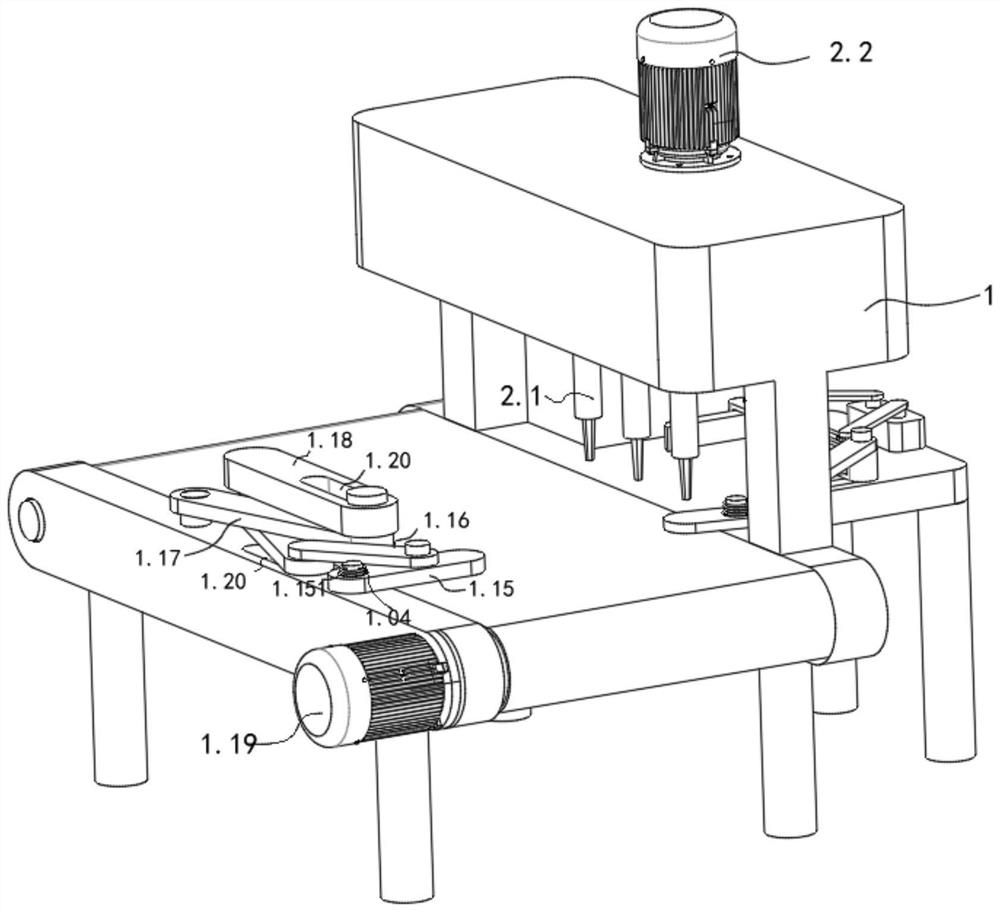
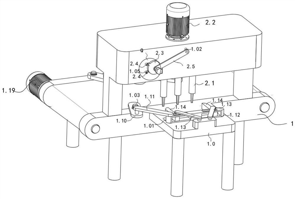
[0045] refer to Figure 1-7b As shown, the present invention provides a pole fastening mechanism, including a frame 1, on which a plurality of screwdrivers 2.1 are slidably arranged; also includes a connecting rod assembly: it is arranged on the frame 1;
[0046] Each screwdriver 2.1 is connected to the connecting rod assembly;
[0047] The expansion and contraction of the connecting rod assembly realizes the adjustment of the horizontal distance between each screwdriver 2.1.
[0048] The connecting rod assembly includes a center seat 2.10 rotatably connected to the frame 1, and a plurality of screwdrivers 2.1 support assemblies are arranged symmetrically in the radial direction of the center seat 2.10.
[0049]Specifically, the frame 1 is used for the connecting rod assembly and the screwdriver 2.1, and the screwdriver 2.1 moves in the horizontal direction of the frame 1, and the horizontal distance between two adjacent screwdrivers 2.1 is adjusted to realize the
[0050] Screwdriver 2.1 is a common tool used to turn screws into place. Screwdriver 2.1 has a thin wedge-shaped head that can be inserted into the slot or notch of the screw head. Rotate clockwise for tight fit, and counterclockwise for Loosen, there are one word (negative sign), cross (positive sign), hexagonal screwdriver and other types, using the working principle of the lever and the axle;
[0051] The connecting rod assembly is installed on the frame 1, and the connecting rod assembly is respectively connected with each screwdriver 2.1, and the connecting rod assembly drives each screwdriver 2.1 to move in the horizontal direction of the frame 1, thereby realizing the adjustment of two adjacent screwdrivers 2.1 the horizontal distance between
[0052] Connecting rod assembly: The connecting rod mechanism, also known as the low pair mechanism, is a type of mechanical component, which refers to a combination of several (more than two) components with definite relative motion connected by a low pair (rotating pair or moving pair) mechanism. There are various forms of motion, such as rotation, swing, movement, and plane or space complex motion, which can be used to achieve known motion laws and known trajectories. In this example, the connecting rod assembly drives each screwdriver 2.1 at the level of the frame 1 In the prior art, the crank is usually used as the active part and rotates at a constant speed, and the connecting rod is used as the driven part to swing back and forth at variable speeds, and the connecting rod is used for plane compound motion. Furthermore, each screwdriver 2.1 is connected through a connecting rod, so that the uniform rotation of the crank drives each screwdriver 2.1 to reciprocate in the horizontal direction of the frame 1 .
[0053] In the process of use, the crank is the active part and rotates at a constant speed, and the connecting rod is the driven part to swing back and forth at variable speeds, and each screwdriver 2.1 is connected to the crank through the connecting rod, and then the constant speed rotation of the crank drives each screwdriver 2.1 Move in the horizontal direction of the frame 1 to adjust the horizontal distance between each screwdriver 2.1, as shown in the figure, it is suitable for assembly parts with different specifications.
[0054] refer to Figure 3-7b As shown, in another embodiment provided by the present invention, each screwdriver 2.1 support assembly slides in the radial direction of the center seat 2.10, and a screwdriver 2.1 is provided on the center seat 2.10 and the screwdriver 2.1 support assembly.
[0055] Wherein, a rotary assembly is arranged between the center base 2.10 and each screwdriver 2.1 support assembly to connect, so that each center base 2.10 drives each screwdriver 2.1 to rotate, and the first driven gear 2.7 is coaxially fixedly connected to the center base 2.10.
[0056] A second driven gear 2.8 is coaxially socketed on the center base 2.10, and a drive rod 2.81 is hinged between the second driven gear 2.8 and each screwdriver 2.1 support assembly.
[0057] Further, there are a plurality of telescopic units sliding in the radial direction of the central seat 2.10; furthermore, the process of moving the support components of each screwdriver 2.1 in the radial direction of the central seat 2.10 is adaptively adjusted by the telescopic units.
[0058] Among them, the frame 1 is rotatably connected with a center seat 2.10, the screwdriver 2.1 support assembly includes a mounting seat 2.14 that is horizontally slidably connected to the frame 1, and the frame 1 is radially symmetrical in the horizontal direction. Adapted snap-in grooves enable each mounting base 2.14 to move in the horizontal direction of the rack 1;
[0059] Specifically, such as Figure 5b And as shown in 5d, the telescopic unit includes a plurality of wheel seats 2.11 and a plurality of axial members 2.12 that are slidably connected to the center seat 2.10, and each axial member 2.12 and each wheel seat 2.11 are alternately arranged on the center seat 2.10. The pieces 2.12 are respectively slidably connected with the corresponding wheel bases 2.11.
[0060] like Figure 5e As shown, each mounting seat 2.14 includes a connecting pin 2.111 connected to the center seat 2.10, and the two ends of the connecting shaft are fixedly connected with support rods 2.110, and each support rod 2.110 is connected with an insertion groove 2.1101 through, and each axial member 2.12 includes a moving block 2.121 slidably connected to the center base 2.10 and two V-shaped bars 2.120 fixedly connected to each moving block 2.121, each V-shaped bar 2.120 is respectively connected to the insertion slot 2.1101 provided on each support bar 2.110 adaptation;
[0061] In the radial direction of the center seat 2.10, a plurality of arc-shaped grooves 2.100 adapted to the connecting pin 2.111 and a plurality of moving grooves 2.101 adapted to the moving block 2.121 are arranged around, and each moving groove 2.101 and each arc-shaped groove 2.100 are arranged in a staggered order, and the inner wall of each moving groove 2.101 is fixedly connected with a second spring 2.102, and the other end of each second spring 2.102 is fixedly connected with the corresponding moving block 2.121.
[0062] The rotary assembly includes a second transmission wheel 2.15 that is rotatably connected to each support rod 2.110, a first transmission wheel 2.14 that is rotatably connected to each mounting seat 2.14, and is nested between each second transmission wheel and each first transmission wheel 2.14. Conveyor 2.13;
[0063] The center base 2.10 is coaxially sleeved with a second driven gear 2.8, and each mounting seat 2.14 is rotatably connected with a first transmission wheel 2.14, and a driving gear is hinged between the second driven gear 2.8 and each first transmission wheel 2.14. Rod 2.81;
[0064] like Figure 3a And as shown in 3b, the center seat 2.10 and the first transmission wheel 2.14 are coaxially fixedly connected with a sleeve 2.9, and each sleeve 2.9 is sleeved with a screwdriver 2.1, and the screwdriver 2.1 and the sleeve 2.9 are connected by the first spring 2.90 ;
[0065] There is a key around the top of each screwdriver 2.1, and the inner wall of each casing 2.9 has a keyway that matches the key. Each casing 2.9 is fixedly connected with a first spring 2.90, and the ends of each first spring 2.90 are respectively It is fixedly connected with the top of each screwdriver 2.1.
[0066] In the process of use, first rotate the second driven gear 2.8, so that the second driven gear 2.8 drives each driving rod 2.81 to rotate, and then makes each driving rod 2.81 drive the mounting seat 2.14 corresponding to it in the horizontal direction of the frame 1 As the length of the conveyor belt 2.13 does not change during the movement of each installation seat 2.14, each axial member 2.12 moves towards the axis of the center seat 2.10 under the action of the transmission belt. Move the rod in the direction of the center, and then the second spring 2.102 is compressed, and each axial member 2.12 drives each wheel seat 2.11 to move towards the direction of the center seat 2.10 during the moving process, thereby realizing automatic tensioning of the transmission belt. When the screwdriver 2.1 moves to a predetermined position, the center base 2.10 rotates, and then the center base 2.10 drives each screwdriver 2.1 to rotate, so as to ensure that each screwdriver 2.1 rotates synchronously to tighten the screw.
[0067] refer to Figure 2d-3a And as shown in 7-7b, another embodiment provided by the present invention further includes a shift assembly, which is rotatably connected to the frame 1, and is driven by the second motor 2.2.
[0068] Wherein, the shift assembly includes a telescopic shaft assembly 2.61 rotatably connected to the frame 1 and a drive gear 2.6 coaxially arranged with the telescopic shaft assembly 2.61.
[0069] The drive gear 2.6 has a first position where the first driven gear meshes and a second position where it meshes with the second driven gear 2.8.
[0070] Between the driving gear 2.6 and the telescopic shaft assembly 2.61, a plurality of arc-shaped rods 2, 65 are arranged around, so as to prevent the driving gear 2.6 from hitting teeth when shifting gears.
[0071] Further, the telescopic shaft assembly 2.61 includes a sleeve shaft 2.610 that is rotatably connected to the frame 1. The sleeve shaft 2.610 is driven by the second motor 2.2. A sliding shaft 2.611 is sleeved inside the sleeve shaft 2.610. The peripheral side of the sleeve shaft 2.610 is opened through There is a limiting groove 2.6101, and the peripheral side of the sliding shaft 2.611 has a limiting pin 2.6110 matching the limiting groove 2.6101. The end of the sliding shaft 2.611 is coaxially provided with a driving gear 2.6, and the sliding shaft 2.611 is connected to the sleeve shaft 2.610. The internal sliding realizes adjusting the position of the driving gear 2.6, so that the driving gear 2.6 has a first position meshing with the first driven gear 2.7 and a second position meshing with the second driven gear 2.8;
[0072] The outer coaxial sleeve of the sliding shaft 2.611 is provided with a sleeve 2.62, and the inner wall of the sleeve 2.62 is provided with an annular groove 2.620 compatible with the limit pin 2.6110, so that the limit pin 2.6110 slides in the annular groove 2.620, and the limit pin The 2.6110 will not disengage from the annular groove 2.620, so that the sleeve 2.62 can drive the sliding shaft 2.611 to slide in its axial direction.
[0073] A plurality of arc-shaped rods 2,65 are hinged between the driving gear 2.6 and the sliding shaft 2.611, and a through hole is provided at the center of the driving gear 2.6 axis, the inner diameter of the through hole is slightly larger than the outer diameter of the sliding shaft 2.611, and the driving gear 2.6 and the sliding shaft 2.611 There are a plurality of arc-shaped rods 2,65 hinged around them; the drive gear 2.6 and the sliding shaft 2.611 are surrounded by a plurality of fourth connecting shafts 2.64, and each fourth connecting shaft 2.64 is sleeved with a fourth torsion spring 2.63 One of the legs of the fourth torsion spring 2.63 is fixedly connected to the fourth connecting shaft 2.64, and the other leg of the fourth torsion spring 2.63 is connected to the arc rod 2,65 corresponding to the arc rod 2,65;
[0074] It also includes: a switching unit, which is arranged on the frame 1 and is used to drive the driving gear 2.6 to switch between the first driven gear and the second driven gear 2.8.
[0075] like figure 2 , 2a , 2d and 2e, the switching unit includes a drive plate 2.3 rotatably connected to the frame 1 and a fourth transmission rod 2.5 hinged on the drive plate 2.3, and the other end of the fourth transmission rod 2.5 is connected to the sleeve 2.62.
[0076] Specifically, there is a transmission shaft 2.621 on the peripheral side of the sleeve 2.62, and a connection groove 1.02 matching the transmission shaft 2.621 is opened through the frame 1, and the transmission shaft 2.621 is located in the connection groove 1.02;
[0077] The frame 1 is located at the position of the driving disk 2.3, and the limiting parts are respectively arranged, and each limiting part is respectively arranged at the first position and the second position;
[0078] like Figure 2-2b As shown, the peripheral side of the driving disc 2.3 has a protrusion 2.30, and the peripheral side of the only driving disc 2.3 on the frame 1 is respectively rotatably connected with two wedge blocks 2.4, and each wedge block 2.4 rotates the frame 1 through the third connecting shaft 1.05 Each third connecting shaft 1.05 is respectively sleeved with a third torsion spring 2.40, one of the legs of each third torsion spring 2.40 is fixedly connected with the third connecting shaft 1.05, and the other leg of each third torsion spring 2.40 is respectively fixed Connected to corresponding wedge blocks 2.4;
[0079] During use, such as Figure 3bAs shown, when the driving gear 2.6 is located at the position meshed with the second driven gear 2.8, the second motor drives the driving gear 2.6 to rotate, and then the second driven gear 2.8 drives each driving rod 2.81 to rotate, and then makes each driving rod 2.81 drives the corresponding installation base 2.14 to move away from the center base 2.10 in the horizontal direction of the frame 1. Since the length of the conveyor belt 2.13 does not change during the movement of each installation base 2.14, the transmission belt Under the action of each axial member 2.12 moves the rod toward the axis direction of the center seat 2.10, and then the second spring 2.102 is compressed, and each axial member 2.12 drives each wheel seat 2.11 toward the center seat 2.10 during the movement. Move in the direction, and then realize the automatic tensioning of the transmission belt, when each screwdriver 2.1 moves to the predetermined position;
[0080] At this time, the user manually switches the position of the driving gear 2.6, that is, rotates the driving disc 2.3 clockwise (from Figure 3b state movement to Figure 3a state), during the rotation of the drive disc 2.3, the protrusion 2.30 on the peripheral side of the drive disc 2.3 exerts force on the wedge block 2.4 abutting against it, so that the wedge block 2.4 rotates, when the protrusion 2.30 and the wedge block 2.4 After disengaging, under the action of the third torsion spring 2.40, the wedge-shaped block 2.4 is reset until the drive plate 2.3 drives the fourth transmission rod 2.5 to move, and then the fourth transmission rod 2.5 drives the casing 2.9 to move, so that the driving gear 2.6 moves to At the position meshed with the first driven gear 2.7, at this time, when the driving gear 2.6 moves from the second driven gear to the position of the first driven gear 2.7, the driving gear 2.6 is in the process of meshing with the first driven gear The undercutting phenomenon will occur, and then the driving gear 2.6 will rotate under the action of the arc rod 2,65, and then the driving gear 2.6 will be meshed with the first driven gear 2.7 under the action of the fourth torsion spring 2.63, thereby avoiding When the driving gear 2.6 is switched, the toothing phenomenon occurs. At this time, the driving gear 2.6 drives the first driven gear 2.7 to rotate, so that the first driven gear 2.7 drives the center seat 2.10 to rotate, and then the center seat 2.10 drives each screwdriver 2.1 to rotate, so as to ensure Each screwdriver 2.1 rotates synchronously to realize screw tightening.
[0081] The pole assembly line also includes a pole assembly mechanism, and the pole assembly mechanism and the pole fastening device are sequentially arranged on the frame 1 .
[0082] refer to Figure 1-7b As shown, the present invention provides a pole assembly mechanism, including a frame 1, which is provided with a conveying assembly for conveying assembly parts, and also includes:
[0083] Pole positioning component: it is set on the frame 1;
[0084] Transmission component: it is arranged on the frame 1, and the transmission component is connected with the pole positioning component;
[0085] When it is detected that the assembly is delivered to a predetermined position, the transmission assembly is triggered, so that the transmission assembly drives the pole positioning assembly to position the pole and assemble the pole on the assembly.
[0086] Specifically, the frame 1 is used to install and support the pole assembly assembly, and the frame 1 is provided with a conveying assembly. Conveyor belt or a plurality of equidistant and linearly arranged conveying rollers, since the conveying components belong to the existing conventional configuration, so there will not be too many details in this application;
[0087] like Figure 1a As shown, in this embodiment, a pulley and a conveyor belt are used to install the assembly. The two pulleys are respectively located at the first and last ends of the frame 1 and the conveyor belt sleeved on the two pulleys. The upper surface of the conveyor belt The frame 1 is just flush, and one of the pulleys is driven by the first motor 1.19 to realize the transportation of the assembly. The first motor 1.19 is fixedly installed on the frame 1, and the first motor 1.19 drives the pulley to rotate to realize the assembly. Parts are conveyed. In this implementation, the conveying component adopts intermittent rotary motion to realize intermittent conveying of assembly parts;
[0088] Assembly: it includes circuit breaker switch mounting base 2.14, isolating switch mounting base 2.14 or a device for assembling the pole of the battery box lamp. The assembly is provided with a plurality of mounting holes that are compatible with the pole. The poles and the mounting holes are set in one-to-one correspondence, and the poles are installed on the assembly by inserting the poles into the mounting holes on the assembly;
[0089] Pole positioning component: it is set on the frame 1 and is used for positioning the pole. In the prior art, fixtures are generally used to position the workpiece. Therefore, in this implementation, the pole positioning component is connected with the transmission component. connection, when the assembly moves to the position corresponding to the transmission assembly (that is, the predetermined position), at this time the pole positioning component positions the pole so that the pole can be inserted into the mounting hole on the assembly, Then realize the assembly of the assembly and the pole;
[0090] Transmission assembly: it is installed on the frame 1, and the transmission assembly is used to drive the pole positioning assembly to position the pole. The transmission assembly converts circular motion into linear reciprocating motion. In the prior art, circular motion can be converted into Mechanisms for linear reciprocating motion include crank rocker mechanism, cam push rod mechanism or other mechanisms that can convert circular motion into linear motion, all of which are used in this implementation;
[0091] In the process of use, when the assembly is transported to the position corresponding to the transmission assembly through the conveying assembly, at this time, the assembly is triggered during the movement of the transmission assembly, so that the transmission assembly drives the pole positioning assembly for positioning on the pole , until the assembly moves to the position corresponding to the pole positioning component. At this time, after each pole corresponds to the mounting hole on the assembly, the pole positioning component drives the pole to move towards the assembly, and then makes The pole is inserted into the mounting hole matched with the assembly to realize the installation of the pole and the assembly.
[0092] The pole assembly mechanism provided by the present invention realizes the positioning of the pole during the conveying process of the assembly, and inserts the pole into the assembly after the assembly moves to assemble. It is simple and reduces the operation steps.
[0093] refer to Figure 2-2d As shown, in another embodiment provided by the present invention, the pole positioning assembly includes a pole placement platform 1.0 arranged on the frame 1; the pole placement platform 1.0 is provided with a clamping unit for positioning the pole, a support The connecting unit and the pushing unit are connected with the clamping unit and the abutting unit respectively.
[0094] Among them, such as Figure 2d As shown, the pole placement platform 1.0 is fixedly installed on the frame 1, and the pole placement platform 1.0 is flush with the conveying plane of the conveying assembly, and the pole is transferred to the pole placement platform 1.0 by the manipulator;
[0095] The clamping unit is used to clamp and position each pole. After the clamping unit clamps and positions the pole, the pushing unit pushes the pole to move toward the assembly, so that the pushing unit moves the pole The column is pushed onto the assembly, so that the pole is plugged into the assembly to achieve alignment
[0096] Further, the pushing unit includes a first trigger lever 1.10 rotatably connected to the frame 1 and a first torsion spring 1.101 arranged between the first trigger lever 1.10 and the frame 1. The first trigger lever 1.10 abuts against the fitting Afterwards, the abutment unit is driven to move, so that the pole is assembled on the assembly part.
[0097] Specifically, the first trigger lever 1.10 is rotatably connected to the frame 1 through the first connecting shaft 1.03, the first connecting connection is fixedly connected to the frame 1, and a first torsion spring 1.101 is sleeved on the outside of the first connecting shaft 1.03, One of the legs of the first torsion spring 1.101 is fixedly connected to the first connecting shaft 1.03, and the other leg of the first torsion spring 1.101 is fixedly connected to the first trigger lever 1.10; The spring 1.101 stores force and then resets through the first torsion spring 1.101;
[0098] Further, the abutment unit is slidably connected to the sliding seat 1.12 on the pole placement platform 1.0, one end of the sliding seat 1.12 is hinged to the first transmission rod 1.11, and the other end of the first transmission rod 1.11 is hinged to the first trigger rod 1.10.
[0099] The clamping unit includes two clamping blocks 1.14 slidably connected to the sliding base 1.12. During the sliding process, the sliding base 1.12 drives each clamping block 1.14 to move in the horizontal direction of the sliding base 1.12 to realize the positioning of each pole.
[0100] A second transmission rod 1.13 is hinged between the sliding seat 1.12 and each clamping block 1.14.
[0101] Specifically, such as figure 1 And as shown in 2c, the pole placement platform 1.0 is provided with two chute 1.01, and the bottom end of the sliding seat 1.12 is fixedly connected with two sliders 1.120 matching with the chute 1.01, each slider 1.120 and each chute 1.01 One-to-one corresponding setting, a first transmission rod 1.11 is hinged on the sliding seat 1.12, and the other end of the first transmission rod 1.11 is hinged on the end of the first trigger rod 1.10;
[0102] The clamping unit includes two clamping blocks 1.14 slidably connected on the sliding seat 1.12, and each clamping block 1.14 slides in the axial direction of the sliding seat 1.12, such as Figure 2c As shown, each clamping block 1.14 is fixedly connected with a mounting block 1.140, and the sliding seat 1.12 is provided with two mounting grooves 1.121 matching the mounting blocks 1.140, and each mounting block 1.140 is set in one-to-one correspondence with each mounting groove 1.121. Make each clamping block 1.14 slide in the axial direction of the sliding seat 1.12;
[0103] A second transmission rod 1.13 (such as figure 2 shown).
[0104] While the pole is grasped and placed on the pole placement platform 1.0 by the manipulator, the assembly is placed on the conveying component for transportation. When the assembly is transported to the position of the first trigger lever 1.10 (that is, the predetermined position), the assembly During the sliding process of the component on the conveying mechanism, the first trigger lever 1.10 is abutted to make the first trigger lever 1.10 rotate, and then the first torsion spring 1.101 stores force during the rotation of the first trigger lever 1.10, so that the first trigger lever 1.10 A trigger rod 1.10 drives the first transmission rod 1.11 to move, and then the sliding seat 1.12 drives the pole to move toward the assembly, and at the same time, the second transmission rod 1.13 drives each clamp when the sliding seat 1.12 moves toward the assembly. Block 1.14 is moved, and then the pole is positioned to prevent the pole from shifting during the assembly process.
[0105] refer to Figure 1a as well as Figure 4-4a As shown, in another embodiment provided by the present invention, it also includes a straightening assembly, which is arranged on the frame 1, and when the assembly is transported to a predetermined position, the straightening assembly is triggered to correct the assembly, so as to realize the insertion of the pole onto the assembly.
[0106] Wherein, the correcting assembly includes an abutment seat 1.18 slidably connected to the frame 1 and a trigger unit, and when the accessory is delivered to a predetermined position, the trigger unit is moved to correct the assembly.
[0107] Further, the trigger unit includes a second trigger lever 1.15 rotatably connected to the frame 1 and an X-shaped hinged frame 1.17 arranged between the frame 1 and the abutment seat 1.18. During the rotation of the second trigger lever 1.15, the X The shape hinge frame 1.17 is deformed, and then the abutment seat 1.18 corrects the assembly.
[0108] Specifically, such as Figure 4aAs shown, a waist-shaped groove 1.20 is provided on the abutment seat 1.18 and the frame 1, and two of the legs of the X-shaped hinged frame 1.17 have pin shafts 1.180 that are compatible with the waist-shaped chute 1.01, and each pin shaft 1.180 Correspondingly located in the first waist-shaped chute 1.01, the other two of the X-shaped hinged frame 1.17 are respectively hinged on the frame 1 or the abutment seat 1.18;
[0109] The frame 1 and the second trigger lever 1.15 are rotated through the second connecting shaft 1.04. The position of the second trigger lever 1.15 is set corresponding to the position of the first trigger lever 1.10. Spring 1.151, one of the legs of the second torsion spring 1.151 is fixedly connected to the second connecting shaft 1.04, the other leg of the second torsion spring 1.151 is fixedly connected to the second trigger lever 1.15, and the second trigger lever 1.15 is hinged with the X shape Frame 1.17 is slidably connected between the legs on the frame 1 and is hinged with a third transmission rod 1.16.
[0110] In the process of use, while the pole is grasped and placed on the pole placement platform 1.0 by the manipulator, the assembly is placed on the conveying assembly for transportation. When the assembly is transported to the position of the first trigger lever 1.10 (ie Predetermined position), the sliding process of the assembly component on the conveying mechanism abuts against the first trigger lever 1.10, at this time, the assembly part moves to the predetermined position and starts the first trigger lever 1.10 and the second trigger lever 1.15 at the same time, and then makes the The first trigger rod 1.10 and the second trigger rod 1.15 rotate at the same time, so that the first torsion spring 1.101 stores force during the rotation of the first trigger rod 1.10, so that the first trigger rod 1.10 drives the first transmission rod 1.11 to move, and the second The second trigger lever 1.15 rotates so that the second torsion spring 1.151 stores force, and then the sliding seat 1.12 drives the pole to move toward the assembly, and at the same time, the sliding seat 1.12 moves toward the assembly, and simultaneously makes the second The trigger rod 1.15 drives the third transmission rod 1.16 to move, and then the X-shaped hinged frame 1.17 drives the abutment seat 1.18 to move in the radial direction of the frame 1, so that the abutting pair of assembly parts is abutted, so that the second transmission rod 1.13 Drive each clamping block 1.14 to move, and then position the pole, so that the pole and assembly parts move towards each other at the same time, avoiding the position shift of the pole during the assembly process, and then completing the assembly of the pole on the assembly.
[0111] Certain exemplary embodiments of the present invention have been described above only by way of illustration, and it goes without saying that those skilled in the art can use various methods without departing from the spirit and scope of the present invention. The described embodiments are modified. Therefore, the above drawings and descriptions are illustrative in nature and should not be construed as limiting the protection scope of the claims of the present invention.

PUM

no PUM

Description & Claims & Application Information

We can also present the details of the Description, Claims and Application information to help users get a comprehensive understanding of the technical details of the patent, such as background art, summary of invention, brief description of drawings, description of embodiments, and other original content. On the other hand, users can also determine the specific scope of protection of the technology through the list of claims; as well as understand the changes in the life cycle of the technology with the presentation of the patent timeline. Login to view more.
Why Eureka
Try Eureka