
Method for reducing potential difference in transformer substation grounding grid caused by impact current
A substation grounding grid and inrush current technology, applied in the high-voltage field, can solve problems such as poor economy, poor operability and accuracy, large reactance of a single copper bar, and failure to meet the design safety limit requirements, and achieve operability and high accuracy, reliable power supply, and the effect of ensuring national energy security
- Summary
- Abstract
- Description
- Claims
- Application Information
AI Technical Summary
Problems solved by technology
Method used
Image

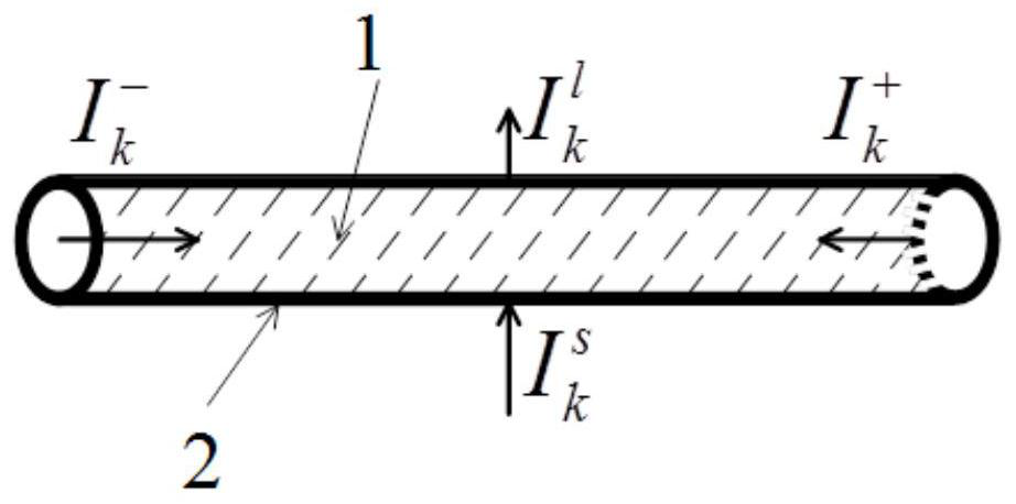
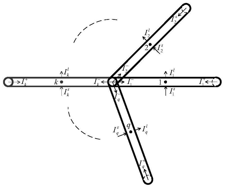
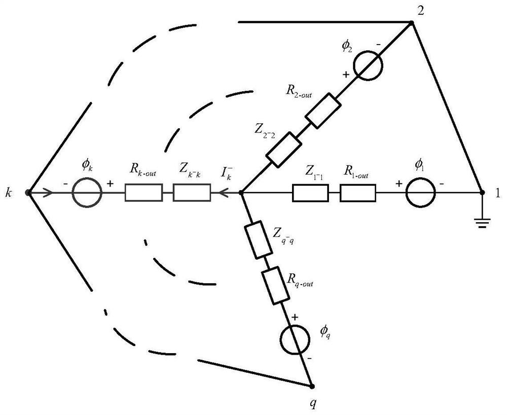
Examples
Embodiment Construction
[0038] In order to make the purpose and technical solutions of the present invention clearer and easier to understand. The present invention will be further described in detail below with reference to the accompanying drawings and embodiments. The specific embodiments described herein are only used to explain the present invention, but not to limit the present invention.
[0039] In the description of the present invention, it should be understood that the terms "center", "portrait", "horizontal", "top", "bottom", "front", "rear", "left", "right", " The orientation or positional relationship indicated by vertical, horizontal, top, bottom, inner, outer, etc. is based on the orientation or positional relationship shown in the drawings, and is only for the convenience of describing the present invention and The description is simplified rather than indicating or implying that the device or element referred to must have a particular orientation, be constructed and operate in a par...
PUM
 Abstract
Description
Claims
Application Information