PWM rectifier pulse width modulation method

A pulse width modulation and rectifier technology, applied in the direction of converting AC power input to DC power output, output power conversion devices, electrical components, etc., can solve the problems of EMI inductance saturation, etc. The effect of suppressing the third harmonic

Pending Publication Date: 2022-07-05
北京航空航天大学江西研究院景德镇分院
View PDF0 Cites 0 Cited by
  • Summary
  • Abstract
  • Description
  • Claims
  • Application Information

AI Technical Summary

Problems solved by technology

[0005] The PWM rectifier adopts the traditional SPWM method, and there is a current spike at startup, and the SVPWM method can suppress the current spike at startup, but because the traditional SVPWM method uses the method of vector synthesis calculation, it will inject a third harmonic wave at steady state , causing saturation of the EMI inductance

Method used


Image

  • PWM rectifier pulse width modulation method
  • PWM rectifier pulse width modulation method
  • PWM rectifier pulse width modulation method

Examples


Embodiment Construction

[0023] The technical solutions in the embodiments of the present invention will be clearly and completely described below with reference to the accompanying drawings in the embodiments of the present invention. Obviously, the described embodiments are only a part of the embodiments of the present invention, but not all of the embodiments. Based on the embodiments of the present invention, all other embodiments obtained by those of ordinary skill in the art without creative efforts shall fall within the protection scope of the present invention.

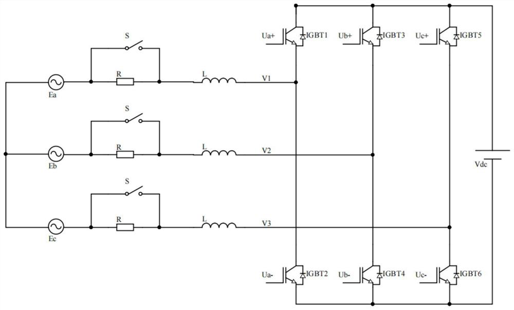
[0024] The schematic diagram of the PWM rectifier circuit is as follows figure 1 where Ea, Eb, and Ec are the three-phase output voltages of the three-phase alternating current, and their effective values ​​are all set to E AC , both are 220V. R is the resistance, S is the switch, L is the inductance, V 1 , V 2 , V 3 is the fundamental frequency voltage, that is, the voltage value here, Ua+, Ua-, Ub+, Ub-, Uc+, Uc- are the PWM con...


PUM


Abstract

The invention discloses a pulse width modulation (PWM) rectifier pulse width modulation method, which comprises the following steps: acquiring three-phase output voltage of three-phase alternating current, and the effective value of the three-phase output voltage is EAC; the PWM signal controls an insulated gate bipolar transistor (IGBT), and at the beginning, based on an SVPWM modulation mode, a three-phase alternating current output end direct current voltage Vdc is monitored at the same time; a three-phase alternating current output end direct current voltage Vdc is collected, the relation between the three-phase alternating current output end direct current voltage Vdc and an effective value EAC is judged, and when the three-phase alternating current output end direct current voltage Vdc is larger than two times of the EAC, an SPWM modulation mode is adopted. According to the method, the SVPWM method is adopted when the PWM rectifier is started, the SVPWM method is switched to the SPWM method when the rectifier reaches the steady state, the current suppression problem at the starting moment of the PWM rectifier and the EWI problem in the steady state are solved at the same time, and the method has the advantages of suppressing the starting current and suppressing the third harmonic when the PWM rectifier reaches the steady state.

Description

technical field [0001] The invention relates to the technical field of power electronics, and more particularly to a pulse width modulation method of a PWM rectifier. Background technique [0002] With the development of power electronics technology, the performance of power semiconductor switching devices has been continuously improved. It has developed from the semi-controlled power semiconductor switches widely used in the early days, such as ordinary thyristors (SCR), to today's fully controlled power switches with different performance and many types. , such as Bipolar Transistor (BIT), Gate Turn Off (GTO) Thyristor, Insulated Gate Bipolar Transistor (IGBT), Integrated Gate Commutated Thyristor (ICCT), Power Field Effect Transistor (IGBTFET) and Field Controlled Thyristor (MCT), etc. The intelligent power module (IPM) developed in the 1990s created a new development direction for power semiconductor switching devices. The advancement of power semiconductor switching d...

Claims


Application Information

Patent Timeline
Patent Type & Authority Applications(China)
IPC IPC(8): H02M7/219H02M1/12
CPCH02M7/219H02M1/12
Inventor 石岩丁艺珂牛燕霞尚晓磊王一轩王娜孙治博
Owner 北京航空航天大学江西研究院景德镇分院
Why Eureka
Try Eureka