Supercharge Your Innovation With Domain-Expert AI Agents!

Gantry crane cable stringing mechanism

A technology for cable racks and gantry cranes, applied in the field of gantry crane cable racking mechanisms, can solve the problems of rain and snow weather, low use efficiency, high installation cost, etc., and achieve the effects of convenient installation, low use cost, and anti-drag wear

Pending Publication Date: 2022-07-22
王林 +1
View PDF0 Cites 0 Cited by
  • Summary
  • Abstract
  • Description
  • Claims
  • Application Information

AI Technical Summary

Problems solved by technology

[0003] In order to overcome the above-mentioned defects of the prior art, the present invention provides a gantry crane cable stringing mechanism to solve the problem that gantry cranes often adopt the method of erecting trolley lines, wire rope hanging cables, slide rail hanging cables or cable reels directly on the ground. High cost, low use efficiency, high installation cost, affected by rain and snow weather, etc.

Method used


Image

  • Gantry crane cable stringing mechanism
  • Gantry crane cable stringing mechanism
  • Gantry crane cable stringing mechanism

Examples


Embodiment 1

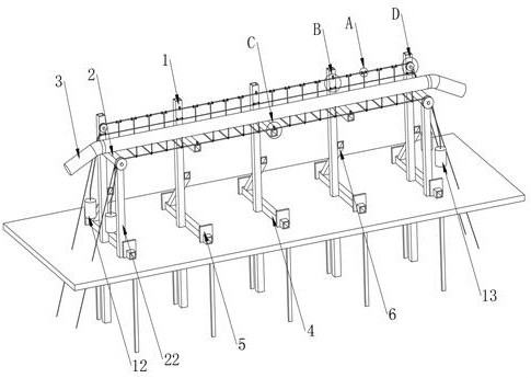
[0032] Refer to the manual attached Figure 1-Figure 7 , a kind of gantry crane cable wiring mechanism of this embodiment includes: a plurality of lateral stabilizer bars 4 and a plurality of uprights 1, cables 3, two pulley shafts one 7 and two pulleys one 8, two pulley shafts two 9 and Two pulleys two 10.

[0033] The column 1 and the stabilizer bar 4 are both made of square tubes. The column 1 is welded on the left side of the stabilizer bar 4. The upper end of the front side of each column 1 is fixedly installed with a support beam 2. 3 is arranged above the support cross bar 2, and the support cross bar 2 is used to receive the cable 3.

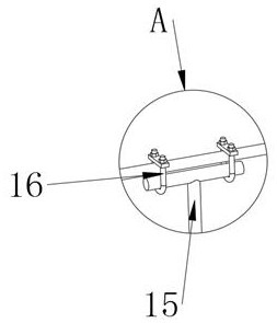
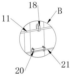
[0034] The two pulley shafts 1 7 are respectively fixed and installed on the upper ends of the front sides of the two uprights 1 on the left and right sides. There is a main suspension wire rope 11 on it, two pulleys one 8 are used to support the main suspension wire rope 11, the depth of the pulley groove in the pulley one 8 is greate...

Embodiment 2

[0044] Refer to the manual attached figure 1 , a gantry hanging cable wiring mechanism of this embodiment, the structure of this embodiment is basically the same as that of Embodiment 1, the difference is that this embodiment is provided with a supporting inclined rod 6 between the lateral stabilizer bar 4 and the upright column 1, One end of the support inclined rod 6 is fixedly connected to the rear side of the upper surface of the stabilizer bar 4 , and the other end of the support inclined rod 6 is fixedly connected to the right side of the column 1 . The support inclined rod 6 ensures that the stabilizer rod 4 The stability when connected with the upright column 1 ensures the stability of the device during use.


PUM


Abstract

The invention discloses a gantry crane cable stringing mechanism, and particularly relates to the technical field of cable stringing, the gantry crane cable stringing mechanism comprises a plurality of transverse stabilizing rods and a plurality of stand columns, and the upper end of the front side face of each stand column is fixedly provided with a supporting transverse rod; a cable; the device comprises two first pulley shafts and two first pulleys, the two first pulleys are rotationally connected with the two first pulley shafts respectively, a main suspension steel wire rope is arranged on the two first pulleys, and the left end and the right end of the main suspension steel wire rope are both fixedly connected with first heavy hammers. The device comprises two first pulley shafts, two second pulley shafts and two second pulleys, the two second pulleys are rotationally connected with the two second pulley shafts respectively, the two second pulleys are provided with auxiliary suspension steel wire ropes, and the left ends and the right ends of the auxiliary suspension steel wire ropes are fixedly connected with second heavy hammers. The device has the advantages of being convenient to install, low in use cost, free of influence of rain and snow weather, resistant to water soaking, electric shock and cable dragging abrasion, capable of eliminating dragging power consumption and capable of automatically pre-tightening and correcting the sag of the cable, and is worthy of being greatly popularized.

Description

technical field [0001] The present invention relates to the technical field of cable wiring, and more particularly, to a gantry crane cable wiring mechanism. Background technique [0002] At present, gantry cranes in outdoor freight yards and processing yards mostly use the method of erecting sliding contact lines, wire rope hanging cables, sliding rail hanging cables or cable reels to lay directly on the ground. In use, it is easy to leak electricity due to the influence of rain and snow, and the sliding contact line needs to be maintained and replaced frequently due to sliding contact friction during use. Therefore, the sliding contact line is generally suitable for indoor workshops; the use of wire rope hanging cable, the flat hanging cable cost is high, The sag of the wire rope cannot be corrected by pre-tightening, and it is not suitable for use in freight yards with long running tracks. The longer the running track, the greater the sag of the wire rope, which will cons...

Claims


Application Information

Patent Timeline
IPC IPC(8): B65H75/38B65H75/44B66C19/00H02G11/02
CPCB65H75/38B65H75/44H02G11/02B66C19/00B65H2701/35
Inventor 王林
Owner 王林
Features
  • R&D
  • Intellectual Property
  • Life Sciences
  • Materials
  • Tech Scout
  • Unparalleled Data Quality
  • Higher Quality Content
  • 60% Fewer Hallucinations
Learn More