Roof window with an improved securing device

A technology of a locking device, dormer, applied to the roof, hinges without pins, roofing, etc.

Inactive Publication Date: 2005-10-19
VKR HLDG AS
View PDF2 Cites 2 Cited by
  • Summary
  • Abstract
  • Description
  • Claims
  • Application Information

AI Technical Summary

Problems solved by technology

This method suffers from the disadvantage that in order to provide proper functionality, the locking device relies on a special design of the controller

Method used


Image

  • Roof window with an improved securing device
  • Roof window with an improved securing device
  • Roof window with an improved securing device

Examples


Embodiment Construction

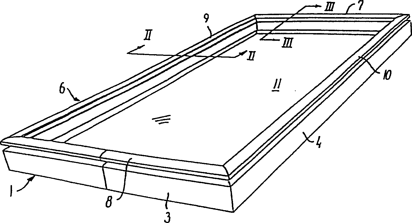
[0023] The roof window illustrated in the accompanying drawings comprises a main frame structure generally designated by the reference number 1 and having an upper member 2, a lower member 3 and two side members 4, 5 shown in the embodiment . Essentially, the dormer window is intended to be mounted to a roof surface by fixedly connecting said main frame structure 1 to said roof structure in a known sense, by means of any suitable Supporting means, such as mounting brackets, are fastened to the main frame side members 4,5.

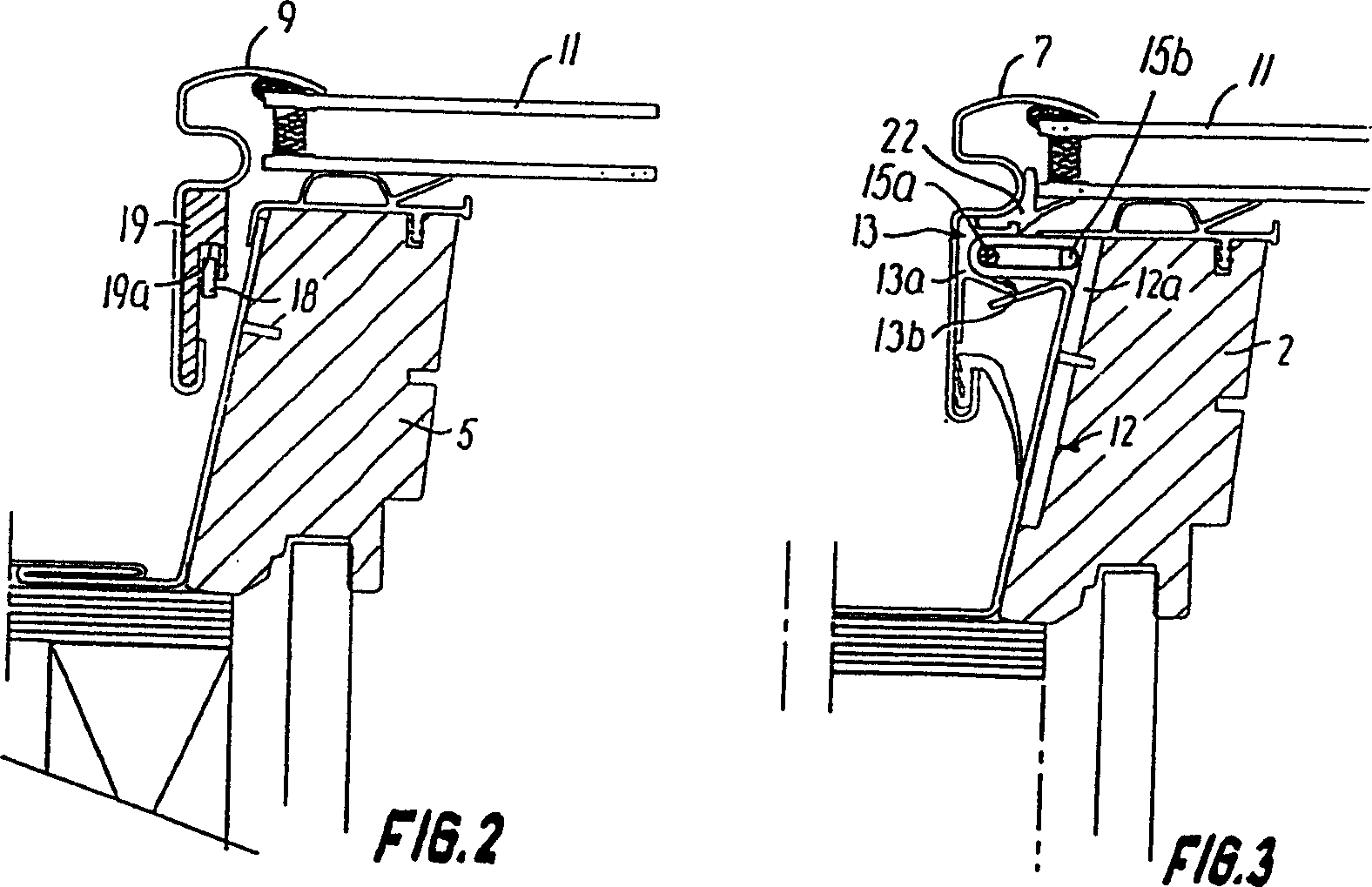
[0024] A window frame structure is generally designated by the reference numeral 6 and has an upper member 7, a lower member 8 and side members 9, 10 in which a glazing element 11 is embedded, in the embodiment shown, the The window frame structure and the above-mentioned main frame structure 1 are connected to each other by means of a hinge connection at the respective upper members 7 and 2 places. In the illustrated embodiment, the above-mentioned hinge ...


PUM


Abstract

The window frame structure of the roof window is secured to the main frame structure (2, 5) within a predetermined range of the opening angle by means of a securing device comprising at least one torsion member (14). The torsion member is torsionally biased in the opening direction of the window and includes engagement means (18) at a distance from the pivot axis for engagement with corresponding engagement means on the window frame structure. The securing device is automatically activated and deactivated during mounting and dismounting of the window frame from the main frame.

Description

technical field [0001] The invention relates to a skylight or roof window comprising a main frame structure for fixed connection with support means of a roof structure, and a window frame structure with a glazing element, said main frame and window The frame structures each have a plurality of members, each of which extends along a longitudinal direction between a first end and a second end; wherein the above-mentioned window frame structure and the main frame structure are connected between the main frame and the main frame structure by at least one hinge The respective first members of the window frame structure are connected to allow the window frame structure to rotate to an opening angle about a pivot axis parallel to the longitudinal direction of said first member relative to the main frame structure, said hinge connection is detachable to allow the window frame structure to be removed from the main frame structure, the at least one connection includes at least one pair ...

Claims


Application Information

Patent Timeline
Patent Type & Authority Patents(China)
IPC IPC(8): E05D7/10E04D13/03E04D13/035E05D1/04E05F1/12
CPCE05F1/123E04D13/0305E04D13/0354E05F1/1215E05D1/04E05Y2900/152
Inventor 科罗思・林格伦柏姬・汉森萨缪尔・霍华德・达莫莫腾・福尔克・瑞文特罗拉尔斯・艾尔德曼
Owner VKR HLDG AS
Why Eureka
Try Eureka