Light-emitting diode lamp

A technology of light-emitting diodes and lamps, which is applied to the semiconductor devices of light-emitting elements, light sources, electric light sources, etc., and can solve the problems of low emission angle, time-consuming and labor-intensive, and inability to project a large angle.

Inactive Publication Date: 2005-12-14
SOLIDLITE CORP
View PDF0 Cites 0 Cited by
  • Summary
  • Abstract
  • Description
  • Claims
  • Application Information

AI Technical Summary

Problems solved by technology

[0003] Existing LED signs, etc. and lighting bulbs place a plurality of LED components on the same plane circuit board. Since the LED light emission has a specific directivity, the emitted light 12 (see figure 1 ) will be projected in a direction perpendicular to the plane of the circuit board, so the emission angle is not high, and it cannot project a large and uniform light like the traditional filament bulb. Lamps arranged in curved surfaces can be improved (see Figure 2). However, when LEDs are combined into curved surfaces, they cannot be soldered automatically through a tin furnace. They need to be manually soldered one by one, which is time-consuming and labor-intensive. It is not easy to manufacture.
In addition, there is an arrangement of multi-layer LED circuit boards, such as patent registration number: 146519. This lamp is composed of multiple circuit boards laminated, and its production is complicated and costly. In view of this, the inventor has been engaged in LED research and development for many years. After several improvements, we finally developed a light-emitting diode lamp for lighting that can evenly project light, and is easy to manufacture and can be directly replaced with existing filament bulbs.

Method used


Image

  • Light-emitting diode lamp
  • Light-emitting diode lamp
  • Light-emitting diode lamp

Examples


Embodiment Construction

[0048] Although the present invention will be described below in accordance with most of the embodiments shown in the drawings, the present invention is not limited to the structures of these embodiments, and it is understood that it includes various design changes described in the scope of the patent application.

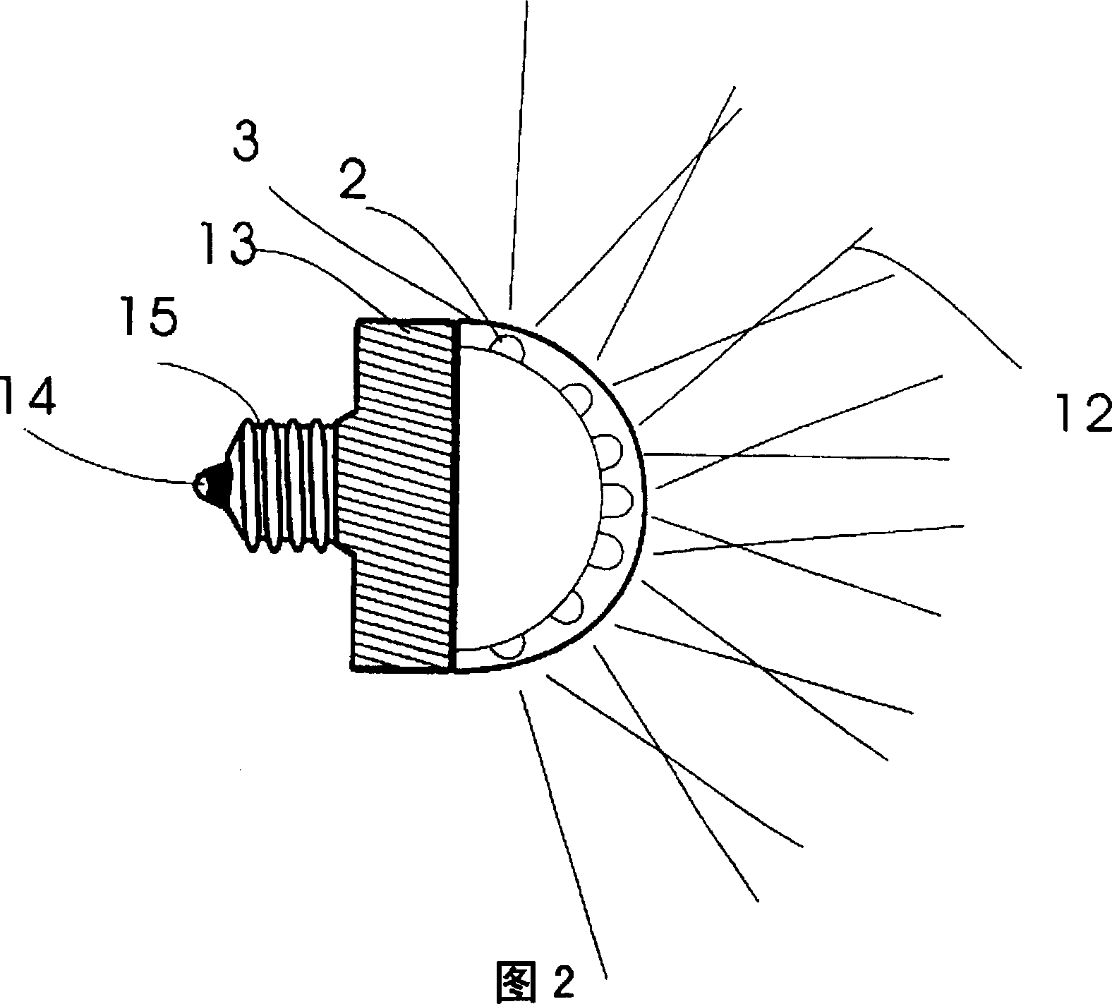
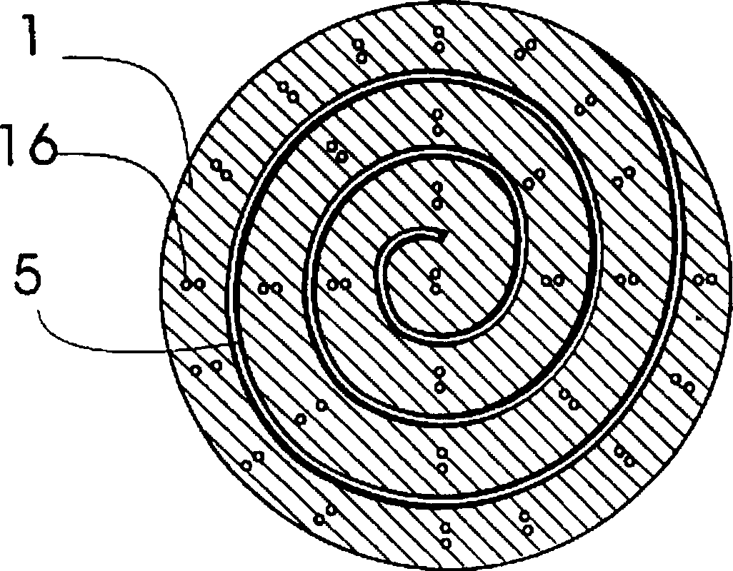
[0049] The light-emitting diode lamp of the present invention includes a plurality of LED elements, a flat circuit board 1, an LED fixing cover 3, a circuit board seating seat 4, and an LED lamp base 13 with a bulb copper head 15 (see Figure 7 ); The present invention cuts or punches a flat circuit board into a multilayer ring shape, which can be roughly divided into "spiral non-crossover manufacturing method". image 3 , Figure 4 , "Spiral jumper manufacturing method" see Figure 8 , Picture 9 , "Concentric circle connection hypotenuse production method" see Figure 13 , Figure 14 , "Concentric Circle Making Method" seeFigure 18 , Figure 19 , The three methods a...


PUM


Abstract

The LED lamp includes several LED elements, one planar circuit board, one LED fixing cover plate, one circuit board installing seat and one copper lamp base. The planar circuit board is first cut or punched to form multilayer ring holes to hold LED elements, and then fixed to the circuit board installing seat to form arced shape. The LED fixing cover plate is used to fixed the positions and irradiating angles of the LEDs. The LED lamp has wide emitting angle and homogeneous light strength and is suitable for lighting.

Description

Technical field [0001] The present invention is a light-emitting diode lamp, in particular to a lamp formed by a plurality of light-emitting diodes (LEDs) on a single plane circuit board, which can be stretched out into a convex arc surface (or concave arc surface) shape. , So that the LED components on the circuit board can be arranged in a curved surface, and fixed by the LED fixing cover and the circuit board seating seat, so that each LED component is placed at a specific angle position, so that each LED component can be optimized The angle of projection can improve the limited light projection angle when the traditional LED elements are arranged in a plane. In addition, the circuit board is flat when the LED elements are welded to the circuit board in the present invention. The tin furnace can be used quickly and has the advantages of convenient manufacturing and assembly. Background technique [0002] Light-emitting diodes have many advantages such as environmental protecti...

Claims


Application Information

Patent Timeline
Patent Type & Authority Patents(China)
IPC IPC(8): F21S6/00
CPCF21K9/232F21Y2115/10
Inventor 陈兴周宗贤
Owner SOLIDLITE CORP
Why Eureka
Try Eureka