A kind of over-flow type sterilization and disinfection device

A sterilizing device and flow-through technology, which is applied in special treatment targets, chemical instruments and methods, water/sludge/sewage treatment, etc., can solve inconvenient water flow dispersion and full-angle sterilization treatment, inconvenient water stable circulation and other problems, to achieve the effect of improving the sterilization effect, reducing the impact, and reducing the obstruction

Active Publication Date: 2022-06-21
MAANSHAN JASON SEMICON CO LTD
View PDF9 Cites 0 Cited by
  • Summary
  • Abstract
  • Description
  • Claims
  • Application Information

AI Technical Summary

Problems solved by technology

[0005] The purpose of the present invention is to provide an over-flow type sterilization and disinfection device to solve the above-mentioned background technology. The existing over-flow type sterilization and disinfection device is inconvenient to realize the stable circulation of water, and at the same time it is inconvenient to disperse the water flow and sterilize at all angles. Dealing with the problem

Method used


Image

  • A kind of over-flow type sterilization and disinfection device
  • A kind of over-flow type sterilization and disinfection device
  • A kind of over-flow type sterilization and disinfection device

Examples


Embodiment 1

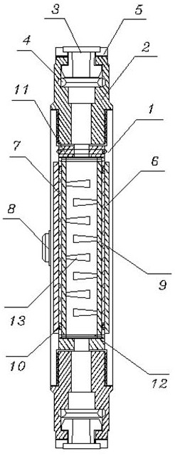
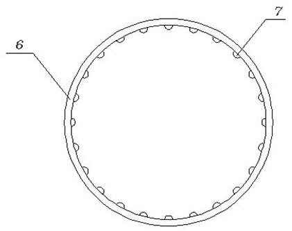
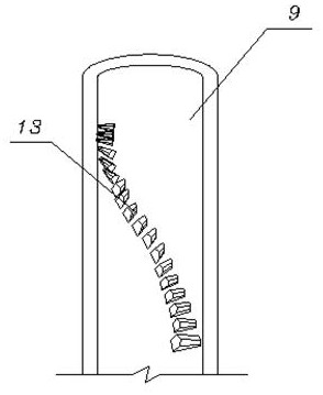
[0032] see Figure 1-5 and Figure 7-8 , including a casing 1, the upper and lower ends of the casing 1 are provided with a quick-insertion interface 2 through threads, and the end of the quick-insertion interface 2 is fixed with an elastic buckle 3, and between the elastic buckle 3 and the inside of the quick-insertion interface 2 is provided with a third A sealing ring 4, and an annular gasket 5 is installed between the elastic buckle 3 and the quick-insertion interface 2, and a third sealing ring 21 is installed between the bottom of the quick-insertion interface 2 and the inner wall of the housing 1; also includes: a circuit board 6 , the circuit board 6 is embedded and installed on the inner wall of the casing 1 in a ring-shaped position distribution, and the ultraviolet lamp beads 7 are fixed on the circuit board 6, and the outer side of the circuit board 6 is connected with an electrical connector 8, and the electrical connector 8 is fixed to the housing. On the outsid...

Embodiment 2

[0034] see Figure 1-8 , including a casing 1, the upper and lower ends of the casing 1 are provided with a quick-insertion interface 2 through threads, and the end of the quick-insertion interface 2 is fixed with an elastic buckle 3, and between the elastic buckle 3 and the inside of the quick-insertion interface 2 is provided with a third A sealing ring 4, and an annular gasket 5 is installed between the elastic buckle 3 and the quick-insertion interface 2, and a third sealing ring 21 is installed between the bottom of the quick-insertion interface 2 and the inner wall of the housing 1; also includes: a circuit board 6 , the circuit board 6 is embedded and installed on the inner wall of the casing 1 in a ring-shaped position distribution, and the ultraviolet lamp beads 7 are fixed on the circuit board 6, and the outer side of the circuit board 6 is connected with an electrical connector 8, and the electrical connector 8 is fixed to the housing. On the outside of the middle p...


PUM


Abstract

The invention discloses an over-flow type sterilization and disinfection device, which comprises a casing. The upper and lower ends of the casing are threaded and installed with a quick-insert interface, and the end of the quick-insert interface is fixed with an elastic buckle. A first sealing ring is provided between the inside of the interface, and an annular pad is installed between the elastic buckle and the quick-plug interface; it also includes: a circuit board, which is embedded and installed on the inner wall of the housing in a ring-shaped position, and the circuit Ultraviolet lamp beads are fixed on the board, a transparent inner cylinder is fixed inside the outer shell, and double sealing rings are installed between the outer sides of the upper and lower ends of the transparent inner cylinder and the inner wall of the outer shell; the reflection unit is arranged on the transparent inner cylinder On the inner wall of the upper top surface, left and right slopes are respectively provided on the left and right sides of the top surface. The over-flow sterilization and disinfection device can conduct spiral diversion to the fluid, realize small obstruction and long circulation of the fluid, and simultaneously disperse and sterilize the fluid from all angles.

Description

technical field [0001] The invention relates to the technical field of water purification equipment, in particular to an over-flow sterilization and disinfection device. Background technique [0002] As the environment changes, there will be many bacteria in water resources. In order to improve the water environment, sterilization and disinfection of water is a conventional method in the prior art. Ultraviolet disinfection is to use ultraviolet rays of appropriate wavelengths to destroy DNA or RNA in microbial cells. The molecular structure of the water can cause the death of growth cells or regenerative cells. The over-flow sterilization and disinfection device uses ultraviolet rays to sterilize the water during the circulation of the water to achieve the effect of sterilization and disinfection, but the existing over-flow sterilization and disinfection device The sterilization and disinfection device has the following problems in use: [0003] In the existing over-flow st...

Claims


Application Information

Patent Timeline
Patent Type & Authority Patents(China)
IPC IPC(8): C02F1/32
CPCC02F1/325C02F2303/04
Inventor 慕永刚郑远志康建陈向东
Owner MAANSHAN JASON SEMICON CO LTD
Why Eureka
Try Eureka