Reflection Cap for Lamp

a technology of reflection cap and lamp, which is applied in the direction of lighting apparatus, lighting device details, lighting and heating apparatus, etc., can solve the problems of not being able to enhance illumination without reducing the irradiation angle of light emitted, the reliability and practicability are badly deteriorated, and the enhancement of illumination is undesirable. limitations, etc., to achieve the effect of enhancing the reflection rate and enlarging the irradiation angle of ligh

Inactive Publication Date: 2014-10-16
LEE DUK MUK +1
View PDF33 Cites 0 Cited by
  • Summary
  • Abstract
  • Description
  • Claims
  • Application Information

AI Technical Summary

Benefits of technology

[0009]Accordingly, the present invention has been made in view of the above-mentioned problems occurring in the prior art, and it is an object of the present invention to provide a reflection cap for a lamp that is capable of enlarging the irradiation angle of light emitted by a fluorescent lamp and enhancing the reflection rate of the light.

Problems solved by technology

After one end of the lamp is passed and moved through the through-hole of one side support plate, however, it is not easy to insertedly fit the other end of the lamp to the through-hole of the other side support plate.
Accordingly, the exchanging time of the lamp is increased to make the reliability and practicability badly deteriorated.
Additionally, the irradiation angle of light emitted by the lamp is restricted by the size of width of the transparent plate having a flat surface, thereby undesirably having the limitations in the enhancement of illumination.

Method used


Image

  • Reflection Cap for Lamp
  • Reflection Cap for Lamp
  • Reflection Cap for Lamp

Examples


Embodiment Construction

[0029]Hereinafter, an explanation on a reflection cap for a lamp according to the present invention will be in detail given with reference to the attached drawing.

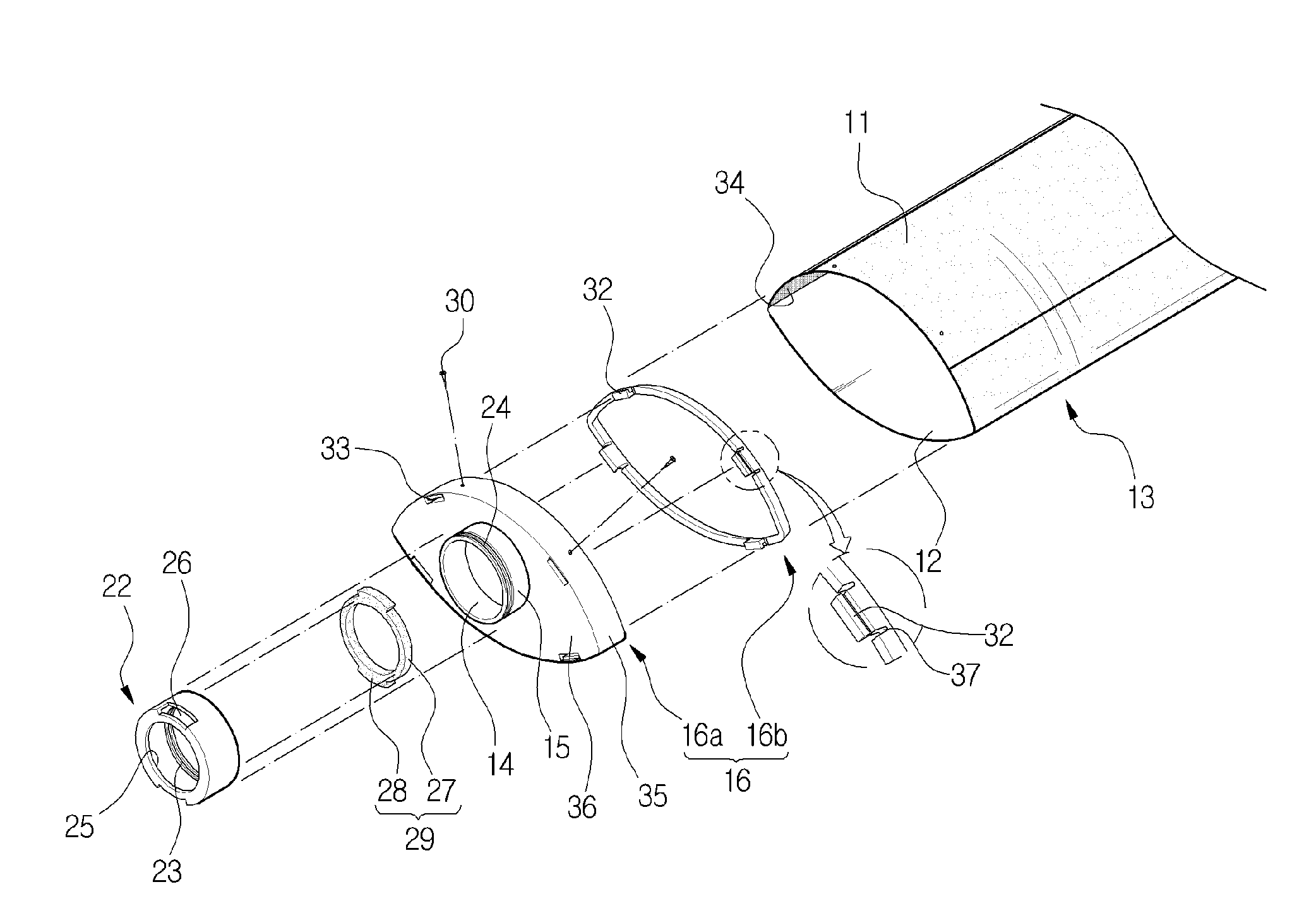
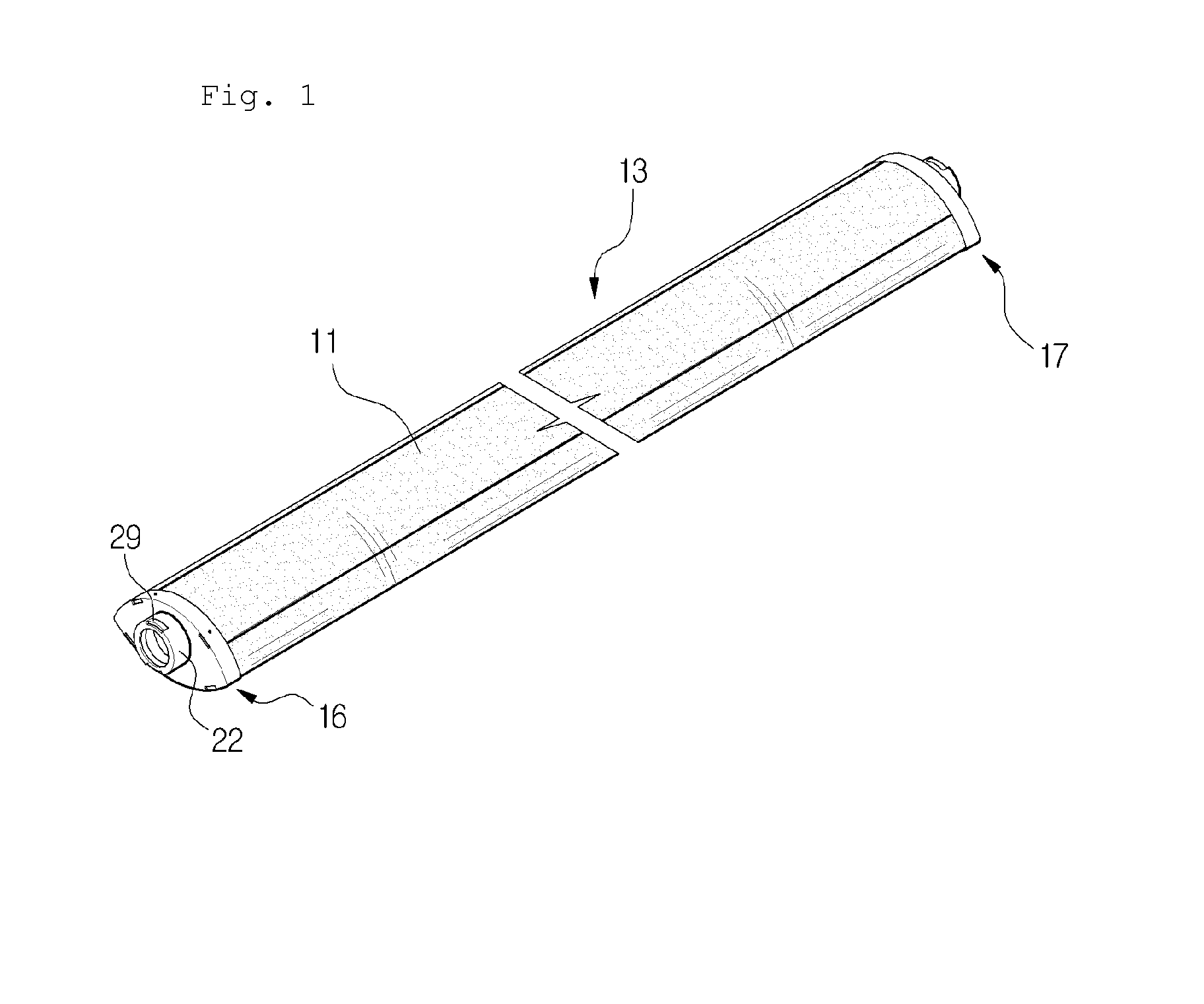
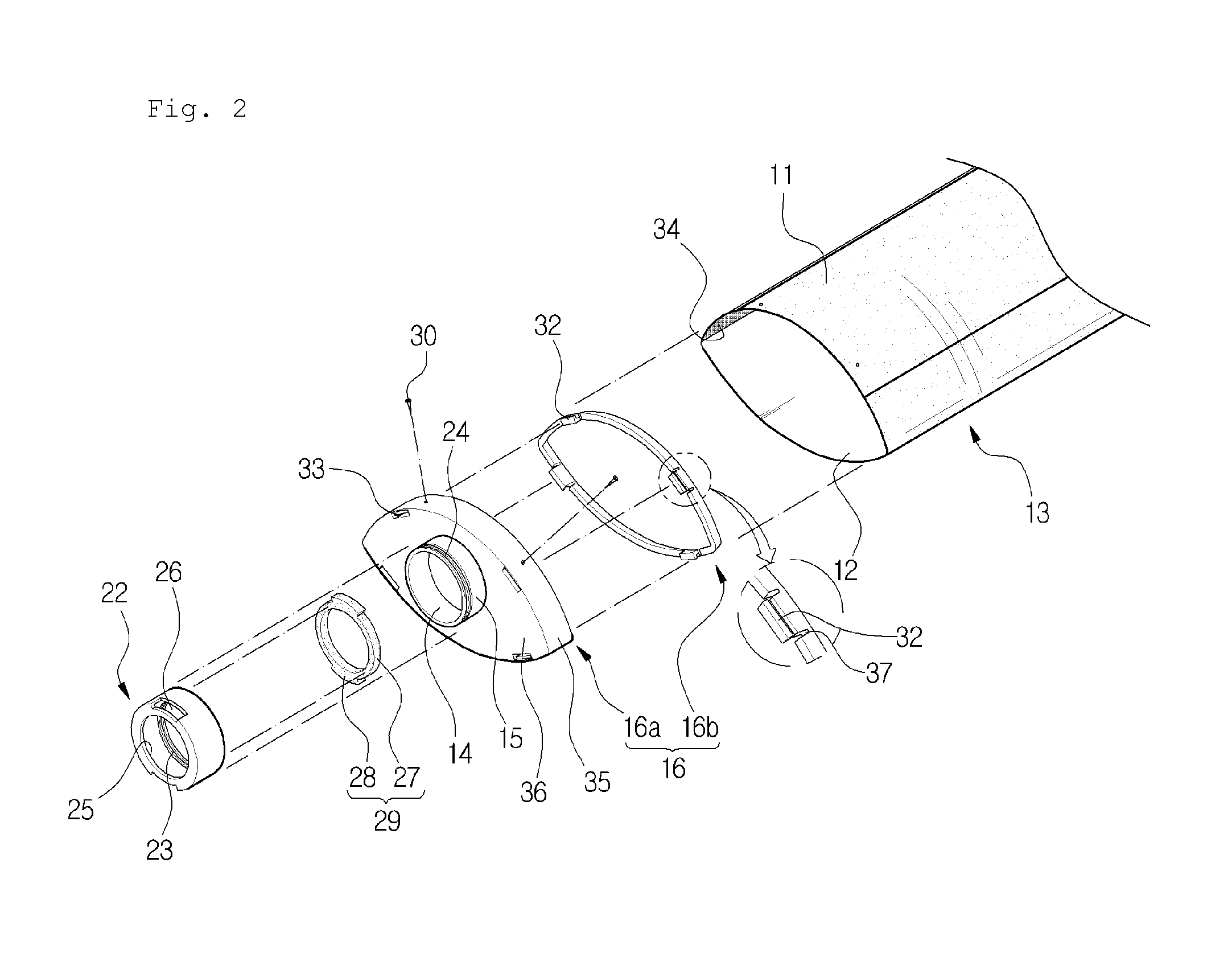
[0030]As shown in FIGS. 1 to 6, a reflection cap for a lamp according to the present invention includes: a body 13 open on both ends thereof and having a reflection plate 11 disposed on the upper portion thereof in such a manner as to reflect the light emitted by a fluorescent lamp 10 (which includes for example a bar-like lamp) housed therein and a transparent plate 12 (which is made of for example a PET material) disposed on the lower portion thereof in such a manner as to be connected to both ends of the underside portion of the reflection plate 11 (alternatively, the transparent plate 12 is partially overlapped to the reflection plate 11 and connected thereto by means of double coated tape) and to transmit the light emitted by the fluorescent lamp 10 therethrough; left and right end caps 16 and 17 detachably fixed to b...


PUM


Abstract

The present invention relates to a reflection cap for a lamp including: a body open on both ends thereof and having a reflection plate disposed on the upper portion thereof and a transparent plate disposed on the lower portion thereof; left and right end caps detachably fixed to both ends of the body and each having a boss protrudedly formed on the outer surface thereof, the boss having a through-hole formed thereon in such a manner as to fittingly insert the fluorescent lamp thereinto; and a fluorescent lamp fixing member rotatably coupled to the boss and adapted to hold and rotate a fluorescent lamp finishing portion clockwisely or counter-clockwisely so as to connect connection terminals of the fluorescent lamp fitted to the through-hole to connection terminals of a socket.

Description

CROSS-REFERENCE TO RELATED APPLICATION[0001]This application is based on and claims priority from Korean Patent Application No. 10-2013-0039350, filed on Apr. 10, 2013 in the Korean Intellectual Property Office, the disclosure of which is incorporated herein in its entirety by reference.BACKGROUND OF THE INVENTION[0002]1. Field of the Invention[0003]The present invention relates to a reflection cap for a lamp, and more particularly, to a reflection cap for a lamp that is capable of easily exchanging a fluorescent lamp.[0004]2. Background of the Related Art[0005]Korean Patent Application Laid-Open No. 10-2012-0061732 discloses a lamp reflection case including: a body having a pair of openings formed on both ends thereof in such a manner as to communicate to each other and a lamp housing space into which a lamp (which means a fluorescent lamp) is housed; a reflector formed on one surface of the interior of the body to reflect the light emitted from the lamp; and a support plate adapte...

Claims


Application Information

Patent Timeline
Patent Type & Authority Applications(United States)
IPC IPC(8): F21V7/00
CPCF21V7/005F21V17/04F21V1/14F21V17/12F21V7/00
Inventor LEE, DUK MUK
Owner LEE DUK MUK
Why Eureka
Try Eureka