Illumination apparatus providing longitudinal illumination

a technology of illumination apparatus and longitudinal illumination, which is applied in the direction of lighting and heating apparatus, instruments, transportation and packaging, etc., can solve the problems of limited inability to achieve modulation of local light flux density, and inability to achieve high frequency intensity modulation in illumination planes. achieve high reflection and uniform illumination

Inactive Publication Date: 2006-11-30
BRIGHT VIEW ELECTRONICS
View PDF18 Cites 110 Cited by
  • Summary
  • Abstract
  • Description
  • Claims
  • Application Information

AI Technical Summary

Benefits of technology

[0012] The present invention is directed to an illumination device that advantageously provides, in a novel and unobvious way, a substantially longitudinal, uniform, and concentrated light output. The illumination device is preferably constructed as a three-part assembly comprising at least one light source unit, a light guide with integrated light extraction feature and an optional light-concentrating optics, and a highly reflective envelope. The light extracting feature can be created during the guide molding process or later by printing. The extraction efficiency of the light-extracting feature varies along the length of the light guide so that a very uniform illumination can be achieved without use of a light-homogenizing section. In another embodiment, the light guide shape is constructed in such a way that light after entering the guide has little chance to be extracted out immediately and output illumination near the light entrance of the light guide is mainly due to the contribution from light rays which are reflected back after reaching the far end of the light guide. Therefore, the uniformity of output light near the light entrance becomes independent of the relative position of the light source unit and its intensity distribution.

Problems solved by technology

However, varying the cross-section of a light guide usually eliminates or limits the possibility of integrating a light-concentrating optics into the light guide.
In addition, an achievable modulation of local light flux density is limited because of possible violation of total internal reflection conditions.
Varying the gap between individual light-extracting features can be used to modulate output light amount as well, but this method may result in an unacceptable high frequency intensity modulation in an illumination plane.
While illuminators prepared using techniques disclosed in the above-mentioned patents may provide some lateral light emission along a light guide, the illumination is generally divergent and a further control of illumination uniformity as required by document reading devices is not possible.
Nevertheless, the light guides shown in these prior patents are generally not capable of being used to illuminate a longitudinal area with a sufficiently uniform intensity.
While the designs according to these prior patents improve the illumination uniformity, using variable cross-section also limit the possibility of using a light concentration feature to control the width and position of an illumination zone or achieve a highly concentrated illumination.
Furthermore, placing a light source deviated sideward from the normal line of the reflection area constrains the freedom of LED packaging and assembly of LED to a light guide.
However, this light homogenizing section unavoidably adds the light guide length, which is not acceptable for some applications with very limited space.
However, a real light guide always has some defects on its surface.
These imperfections can cause light leakage, degrading output light intensity.
Although the U.S. Pat. No. 6,464,366 acknowledged and claimed the use of reflection means outside the light extracting feature to catch the leaked light, it did not teach how to implement such kind of reflection means.

Method used


Image

  • Illumination apparatus providing longitudinal illumination
  • Illumination apparatus providing longitudinal illumination
  • Illumination apparatus providing longitudinal illumination

Examples


Embodiment Construction

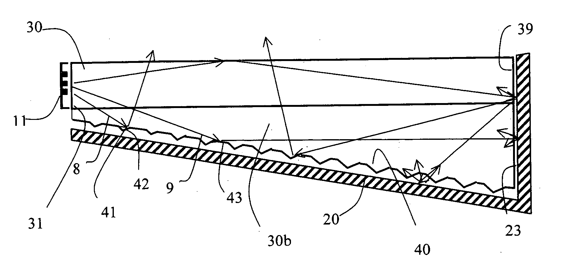
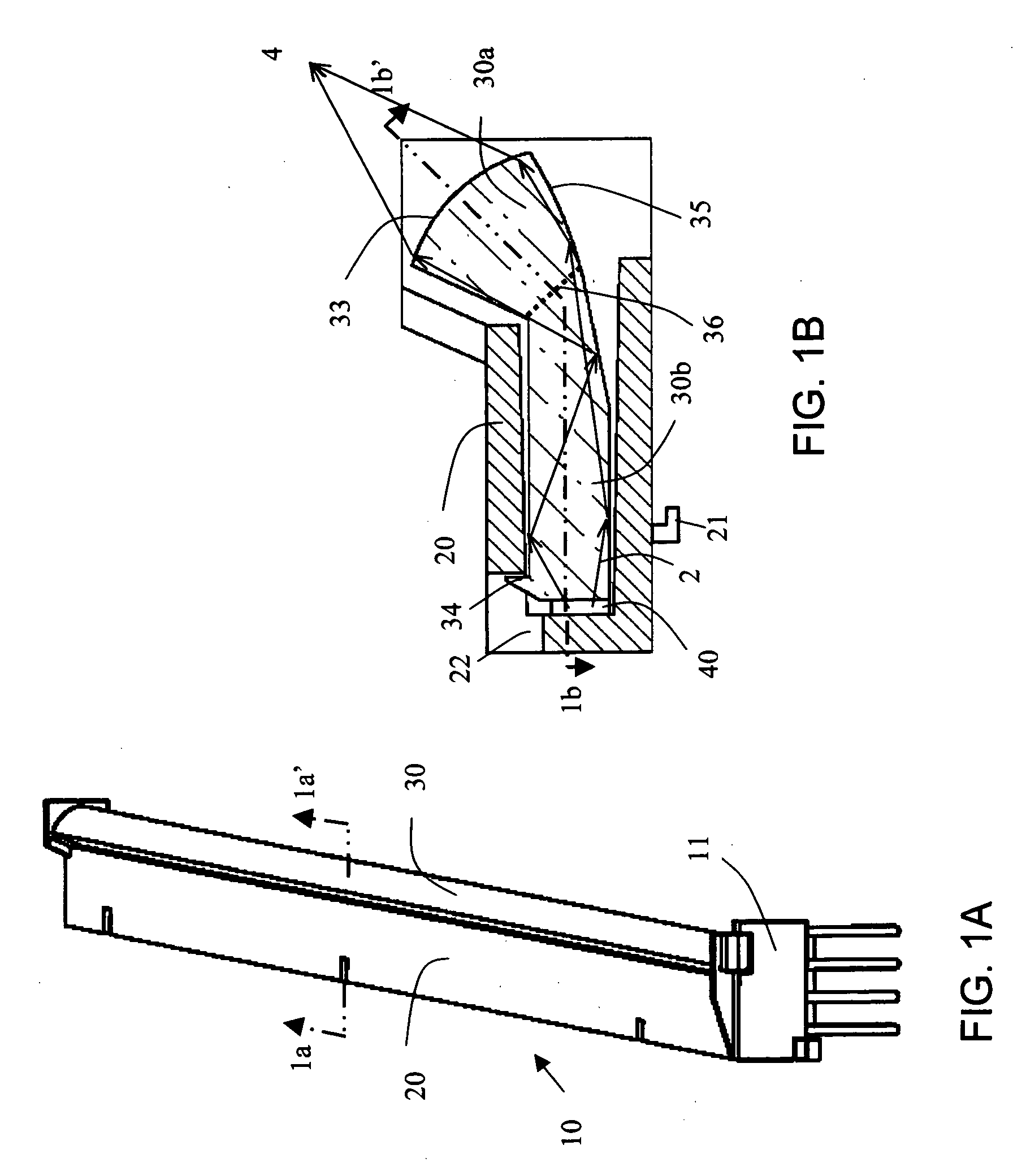
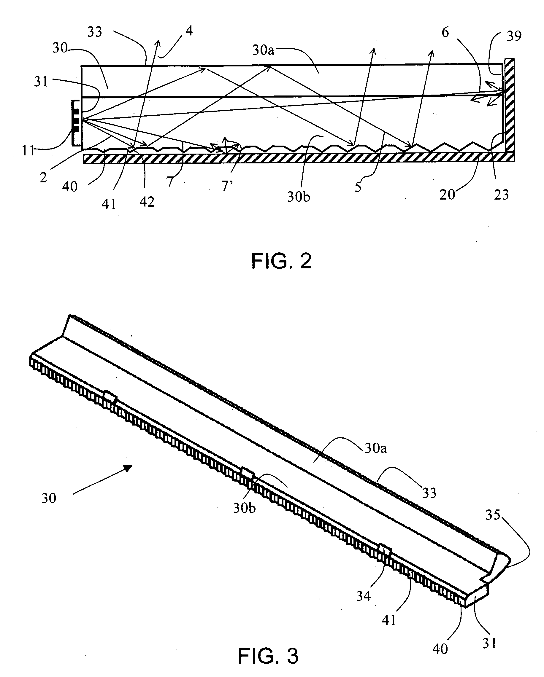
[0025] The present invention is directed to an high efficient illumination device that advantageously provides, in a novel and unobvious way, a substantially longitudinal, uniform, and concentrated light output. The illumination device is preferably constructed as a three-part assembly comprising at least one light source unit, a light guide and a reflective envelope that receives the light guide. The light guide has first and second optically coupled sub-guides. A light-extracting feature is integrated into the second sub-guide and optically coupled to an entrance opening of the first sub-guide. The light-extracting feature redirects light within the light guide to form an effective light-emitting object at the entrance opening. Light from that effective light emitting object is projected out of the light guide by light-concentrating optics provided by the internal surfaces of the first sub-guide. The first sub-guide has a predetermined cross-sectional shape and a substantially uni...


PUM


Abstract

An illumination device using an innovative design to provide a uniform, highly concentrated and substantially longitudinal illumination. The device includes, at least one light source unit, a compound light guide with a built-in light-extracting feature and a reflective envelope. The compound light guide comprises two optically coupled sub-guides. A first sub-guide has a constant cross-section area with a profile optimized for an integral light-concentrating optics, and a second sub-guide has a varying cross-section area for controlling local light flux density inside the light guide and providing assembly means. Said light extracting feature having variable light extraction efficiency improves illumination uniformity at an area close to a light input end of the light guide without displacing a light source from the central normal line of a light-extracting feature. The extracted light from the light-extracting feature forms an effective light-emitting object with a constant width for the integral light-concentrating optics and therefore, the width of the light-extracting feature can be modulated to improve illumination uniformity without affecting the width of illumination. The reflective envelope recycles all light leaked out of the light guide and protects the light guide from environmental contamination and provides mechanical interface between the device and the application assembly.

Description

FIELD OF THE INVENTION [0001] The present invention relates generally to a low-profile illuminating device employing a light guide to provide a longitudinal, uniform and highly concentrated illumination. BACKGROUND OF THE INVENTION [0002] Document processing devices such as scanners, fax-machines and electronic copy machines need a uniform, efficient and sufficiently intense longitudinal illumination on a target document. As a consequence of the requirement for both efficiency and intensity, a longitudinal illumination is preferred. The required illumination can be provided by a discharge tube such as a fluorescent lamp or a light-emitting-diode (LED) array consisting of a plurality of LEDs. Recently, with the advance in the LED technology and the sensor technology, the required illumination flux can be supplied by a couple of LEDs. Therefore, there is a need for an illumination device which can provide a longitudinal illumination for document processing devices by using a limited n...

Claims


Application Information

Patent Timeline
Patent Type & Authority Applications(United States)
IPC IPC(8): G02B6/10
CPCF21S48/215F21S48/2225G02B6/0036H04N1/02895H04N1/02815H04N1/02835G02B6/0055F21S43/14F21S43/235
Inventor HWANG, GWO-FENGLEE, SHIH-YEN
Owner BRIGHT VIEW ELECTRONICS
Why Eureka
Try Eureka