Diffuse reflective articles

a reflective article and diffuser technology, applied in the field of diffuse reflective articles, can solve the problems of many tests being inaccurate in measuring absolute absolutes, prohibitively large overall thickness required to diffusely reflect most of the light,

Inactive Publication Date: 2003-06-26
3M INNOVATIVE PROPERTIES CO
View PDF27 Cites 108 Cited by
  • Summary
  • Abstract
  • Description
  • Claims
  • Application Information

AI Technical Summary

Benefits of technology

[0006] It is known from optical physics that incident light or radiation is significantly scattered and diffusely reflected by an article that is made from two or more non-absorbing materials having different refractive indices if the structure of the article provides appropriately sized regions of each material. To make an efficient diffuse reflector, the size (i.e. the cross-sectional width or height) of the light-scattering regions or sites of the article should be about the same as the wavelength of the light to be reflected. If the sizes of the scattering sites are a great deal smaller than the wavelength of interest, the light passes through the article. If the sizes are a great deal larger, the overall thickness required to diffusely reflect most of the light is prohibitively large. It is also known that the efficiency of the reflector is increased as the difference in refractive index of the two media is increased.
[0007] The present invention provides a diffuse reflective article incorporating microporous layers using TIPS technology. The diffuse reflective article is preferably flexible and can diffusely reflect radiation, e.g., visible light having a wavelength of from 380-730 nanometers (nm), more efficiently than most other known reflectors of similar thickness. The diffuse reflective article can provide improved reflectivity with raw materials that are both inexpensive and readily available. The measured reflectivity of the diffuse reflective article is dependent on the test method used, as many tests are inaccurate in measuring absolute reflectance values approaching 100%. In addition, extremely high diffuse reflectivity of these TIPS articles has been found in the near infrared and ultraviolet wavelengths.
[0008] The present invention further provides an improved diffuse reflector having a reduced thickness while maintaining a high absolute reflectance value. This reduced thickness allows for creation of various products having a narrowed profile, including LCD illumination systems.

Problems solved by technology

If the sizes are a great deal larger, the overall thickness required to diffusely reflect most of the light is prohibitively large.
The measured reflectivity of the diffuse reflective article is dependent on the test method used, as many tests are inaccurate in measuring absolute reflectance values approaching 100%.

Method used


Image

  • Diffuse reflective articles
  • Diffuse reflective articles
  • Diffuse reflective articles

Examples


example 1

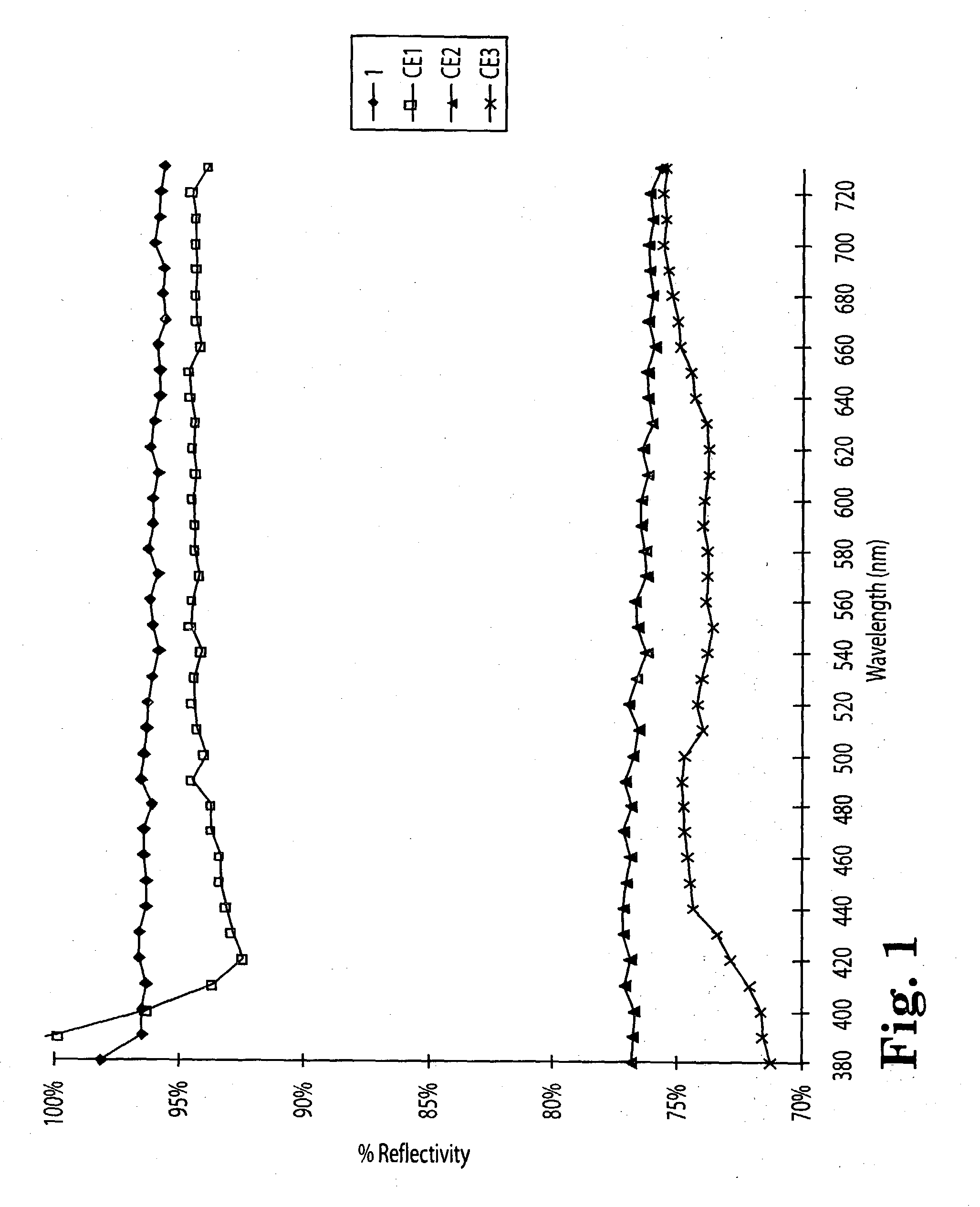
[0110] Example 1 and Comparative Examples 1-3 were tested for their reflectance spectra by method 1 which are shown in FIG. 1. The spectra for Comparative Example 2 was taken of a region that approximated a thickness closer to 150 .mu.m. The reflectivity of better than all the comparative examples across most of the visible light spectrum.

examples 2 and 3

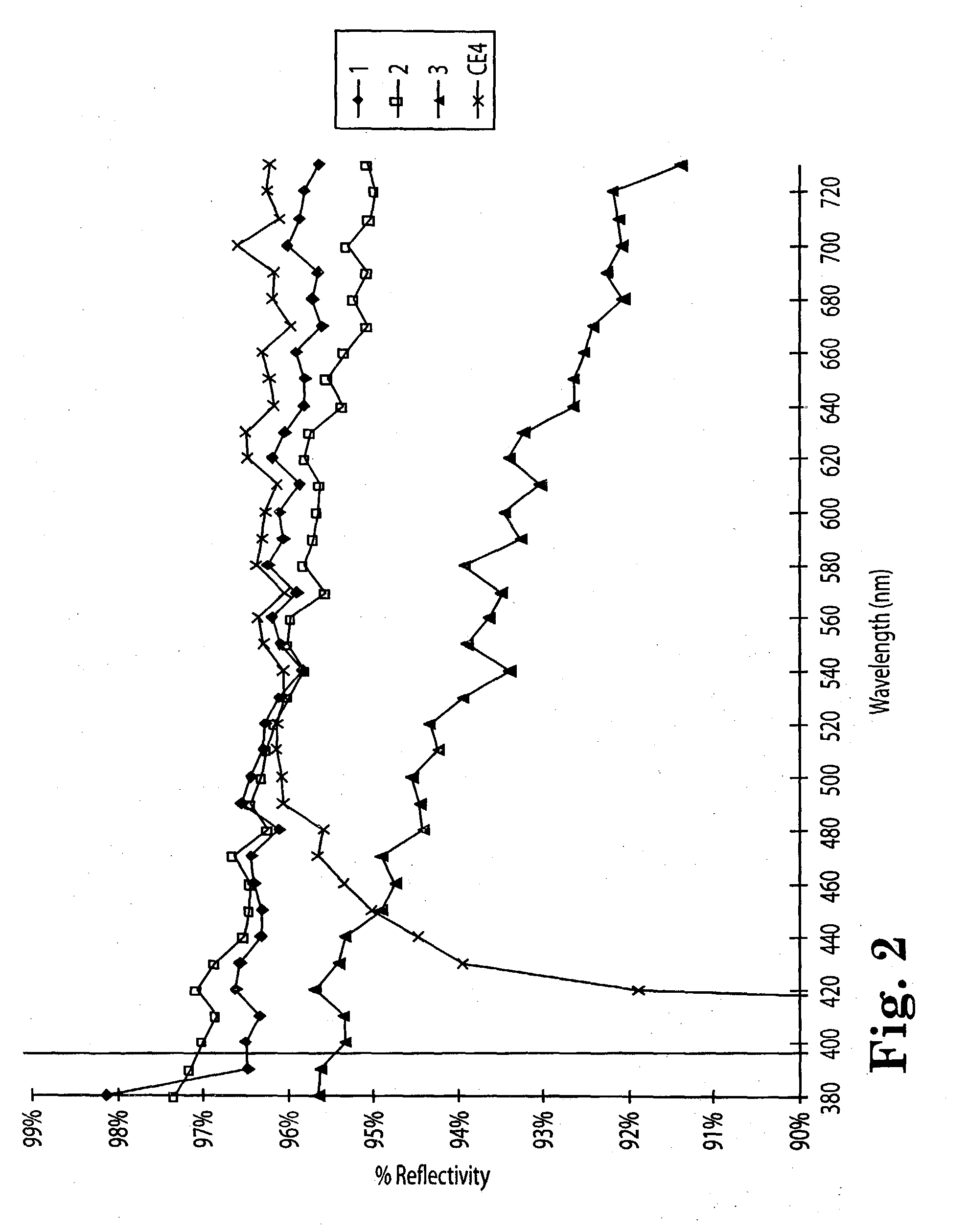
[0114] Examples 2 and 3 and Comparative Example 4 were tested for their reflectance spectra which are shown in FIG. 2 together with that of Example 1. The thickest inventive reflector (Example 1) was more reflective than Comparative Example 4 until about 530 nm visible light wavelength, but was slightly less reflective than CE4 at higher wavelengths. Comparative Example 4 was also less reflective than inventive Examples 1 and 2 until about 520 nm wavelength and was less than 3% more reflective at 550 nm than Example 3, a film having a significantly lower processing cost.

examples 4-6

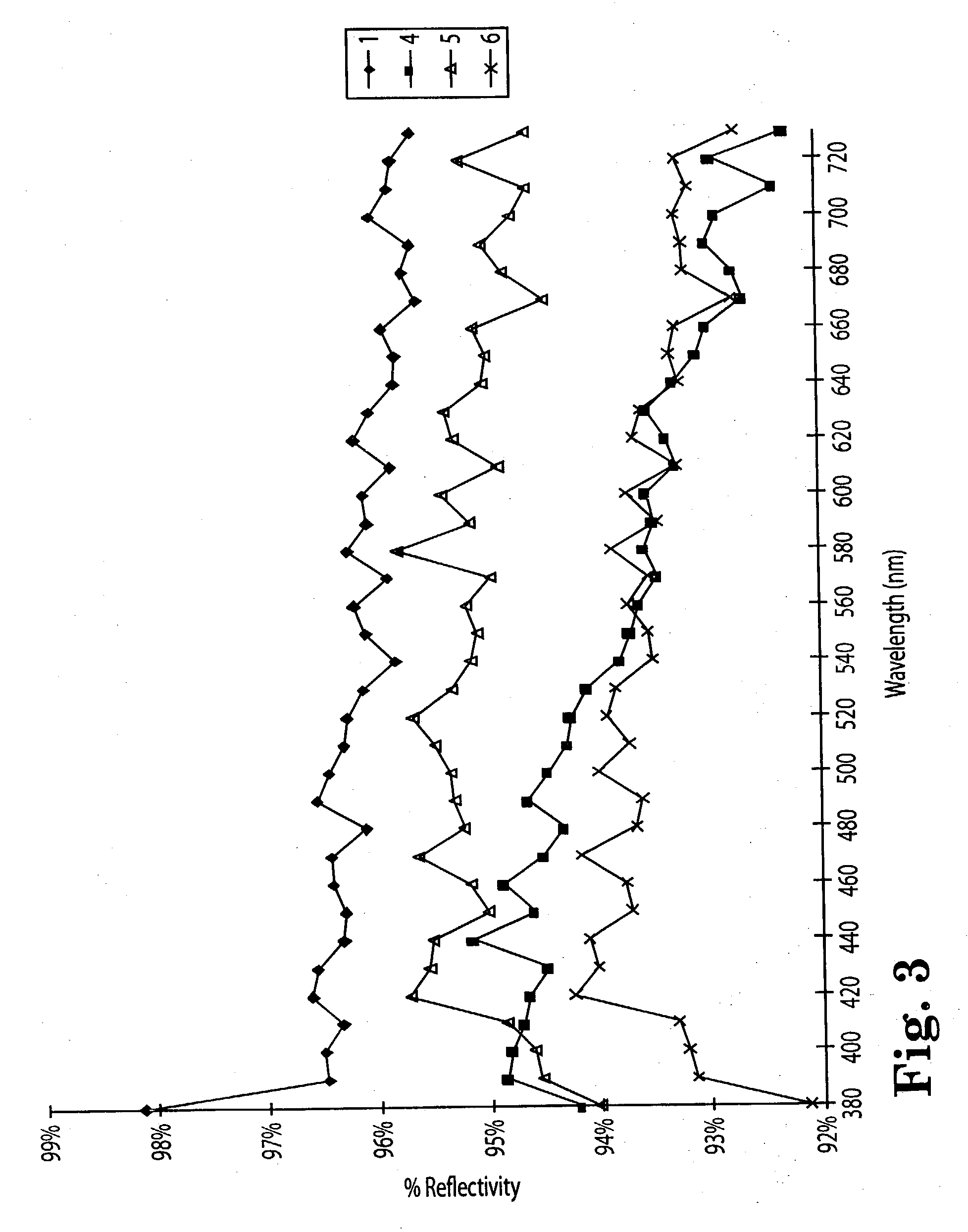
[0115] The effect of diluent extraction was demonstrated on various microporous film constructions.

[0116] Example 4 was prepared in a manner similar to Example 1 except that the casting wheel speed was increased to provide a construction with a thickness of about 205 .mu.m (8 mil) and the washing time and drying time was decreased proportionately.

[0117] Examples 5 and 6 were made using the same polymer and diluent as Example 1. The two materials were introduced into the extruder to provide a composition of 50% by weight of the polymer and 50% by weight mineral oil The nucleating agent was provided at 750 ppm and 1000 ppm, respectively. The overall feed rate was 20.5 kg / hr. The polymer was heated to 271.degree. C. in the extruder to melt and, after mixing with the oil, the temperature was maintained at 177.degree. C. during the extrusion. The melt was extruded through a 30.5 cm-wide coat hanger slit die and cast as a transparent film onto a casting wheel maintained at 66.degree. C. a...


PUM

PropertyMeasurementUnit
reflectivityaaaaaaaaaa
wavelengthaaaaaaaaaa

Abstract

Diffuse reflective materials proximate to a structure formed by thermally induced phase separation of a thermoplastic polymer and a diluent providing enhanced flexibility and reflectivity especially in the visible wavelengths of 380-730 nanometers are described. Such materials find a wide variety of application among combinations with other reflective layers. The diffuse reflective articles are useful in backlight units of liquid crystal displays, lights, copy machines, projection system displays, facsimile apparatus, electronic blackboards, diffuse white standards, photographic lights and the like.

Description

[0001] This is a continuation-in-part of Application Ser. No. 08 / 957,558, incorporated herein by reference in its entirety.[0002] The present invention relates to improved reflective articles, including improved diffuse reflective articles formed from a thermoplastic polymer and a diluent employing thermally induced phase separation technology (TIPS).[0003] Diffuse reflection provides reflective light luminance at many angles, in contrast to specular or mirror reflection in which light is reflected back only at an angle equal to that of the incident radiation. Typical diffuse reflectors, used for example as white standards for various light measuring test instruments, are made of white inorganic compounds (such as barium sulfate or magnesium oxide) in the form of pressed cake or ceramic tile, all of which are expensive, stiff, and brittle. Other existing diffuse reflectors include (1) microvoided particle-filled articles that depend on a difference in index of refraction of the part...

Claims


Application Information

Patent Timeline
Patent Type & Authority Applications(United States)
IPC IPC(8): C08J5/18C08J9/00C08J9/26F21V7/22F21V8/00G02B5/02G02B5/08G02B6/00G02F1/1335
CPCC08J5/18C08J2323/02F21S48/1394F21V7/22G02B5/021G02B5/0247Y10T428/24355G02B6/0031G02B6/0046G02B6/0051G02B6/0065G02B6/0096G02B5/0284F21S41/37F21V7/24F21V7/28Y10T428/249953Y10T428/249954Y10T428/249958Y10T428/249978Y10T428/249986Y10T428/24999Y10T428/249995Y10T428/249997
Inventor KRETMAN, WADE D.KAYTOR, SCOTT R.
Owner 3M INNOVATIVE PROPERTIES CO
Why Eureka
Try Eureka