
Ionic Capacitive Laminate and Method of Production

a capacitive laminate and capacitive technology, applied in the field of flexible ionic electroactive polymer, can solve the problems etc., and achieve the effect of unprecedented repeatability, cost, quantity

Inactive Publication Date: 2018-02-15
UNIV OF TARTU
View PDF0 Cites 5 Cited by
  • Summary
  • Abstract
  • Description
  • Claims
  • Application Information

AI Technical Summary

Benefits of technology

The patent text describes an invention of a membrane with electrodes that can be used to create smart textiles with integrated actuators, sensors, and energy storage units. The membrane is reinforced with a fabric core and can be made in a virtually unlimited industrial scale quantity. The use of a fibrous substrate allows for the creation of smart textiles with embedded ICL actuators. The invention also provides a method for making the membrane without an ionic liquid, which can be beneficial for industrial processes and can increase the number of suitable polymer materials for membrane production. The membrane and electrode solutions can be applied using spraying or painting, and the cycle of applying and evaporating solvent can be repeated to achieve the required thickness. Overall, the invention provides an efficient and scalable solution for producing shiny and functional textiles with embedded actuators.

Problems solved by technology

The improved DAP is demonstrated in a semi-laboratory-scale, however, this process is fully up-scalable to automated, industrial roll-to-roll conveyors for preparing ICLs at unprecedented repeatability, cost, and quantity.

Method used


Image

  • Ionic Capacitive Laminate and Method of Production
  • Ionic Capacitive Laminate and Method of Production
  • Ionic Capacitive Laminate and Method of Production

Examples


Embodiment Construction

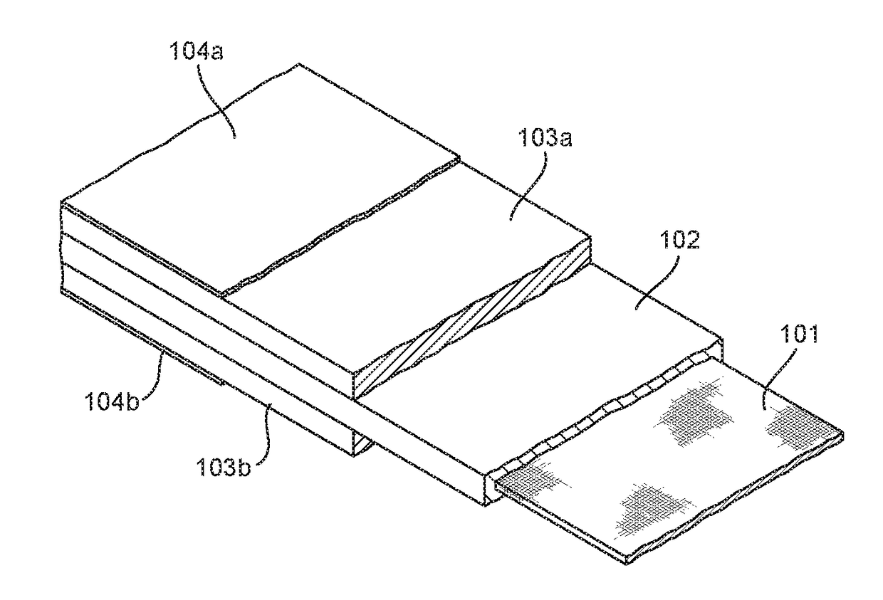
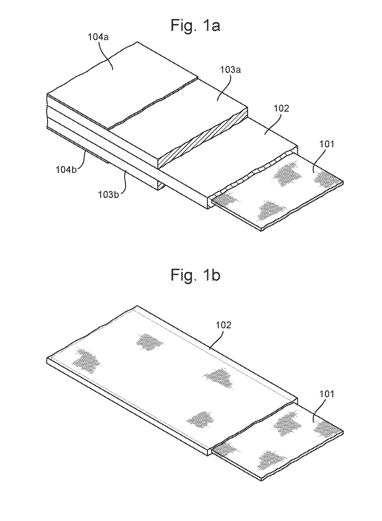
[0038]An embodiment of the invention is shown in FIG. 1a, where a strip of ICL material comprising a core of reinforcing web 101, a polymer membrane 102, electrodes 103a, 103b and current collectors 104a, 104b are shown.

[0039]The reinforcing web 101 is preferably an inert, thin, inelastic, and electrically nonconductive mesh. However, it could be made of any material that does not dissolve in the solvents used during the fabrication process. This reinforcement grid 101 forms the middlemost layer of the ICL. A glass fibre mesh of thickness 30 to 100 micrometres (microns) is suitable as the reinforcement grid 101. The reinforcing web 101 preferably has mechanical properties of strength and flexibility, therefore a woven fabric or textile having a weft and warp of single filaments or filament bundles is suitable. The proportions of the material used for the reinforcing web 101 are selected so that the web 101 is permeable to liquid but having mesh openings that allow liquid to bridge t...


PUM

PropertyMeasurementUnit
thickaaaaaaaaaa
thicknessaaaaaaaaaa
thicknessaaaaaaaaaa

Abstract

The application relates to flexible ionic electroactive polymer (IEAP) laminates also known as ionic capacitive laminates (ICLs) particularly used for actuators, sensors or capacitors. More specifically, the invention relates to ICLs capable of fabrication on an industrial scale. An ionic electroactive polymer laminate suitable for use as an actuator is described, comprising opposing planar electrodes separated by an electrode-separating layer, wherein the electrode separating layer comprises a flexible porous reinforcing web suitable for supporting the laminate during fabrication, the electrode-separating layer further including an ion permeable polymer membrane within the pores of the reinforcing web. A method of producing an ionic electroactive polymer laminate suitable for use as an actuator is also described, comprising the steps of producing a planar electrode-separator by supporting a flexible, porous reinforcing web so that it is taught, impregnating the reinforcing web with a membrane solution that includes a polymer suitable for forming an ion permeable membrane, a pore-forming liquid and a solvent, evaporating the solvent to form an ion permeable membrane within the structure of the reinforcing web, the method further including the steps of coating each side of the planar electrode-separator with an electrode solution comprising material suitable for forming electrodes and an electrode solvent, evaporating the electrode solvent to form planar electrodes separated by the electrode-separator.

Description

BACKGROUNDField of the Invention[0001]The invention relates to flexible ionic electroactive polymer (IEAP) laminates also known as ionic capacitive laminates (ICLs) particularly used for actuators, sensors or capacitors. More specifically, the invention relates to ICLs capable of fabrication on an industrial scale.Description of Related Art[0002]Electroactive polymers (EAPs) are polymers that exhibit a change in size or shape when stimulated by an electric field. The most common applications of this type of material are in actuators and sensors. A typical characteristic property of an EAP is that they will undergo a large amount of deformation while sustaining large forces. EAPs have applications in devices and systems involving smart materials inherently capable of changing dimensions and / or shape in response to suitable electrical stimuli, so as to transduce electrical energy into mechanical work. They can also operate in reverse mode, transducing mechanical energy into electrical...

Claims


Application Information

Patent Timeline
Patent Type & Authority Applications(United States)
IPC IPC(8): F03G7/00
CPCF03G7/005B32B5/02H01M8/1018Y02E60/50
Inventor MUST, INDREKJOHANSON, URMASBARANOVA, INNAKAASIK, FRIEDRICHAABLOO, ALVO
Owner UNIV OF TARTU
Learn More