Unmanned aerial vehicle formation performance system based on UWB location and implementation method thereof

An implementation method and a technology of drone formation, applied in the field of UWB positioning-based drone formation performance system, can solve the problems of high cost, limited number of drones, large size and inability to carry micro drones, etc., and achieve the goal of reducing prices Effect

Active Publication Date: 2018-08-24
XIAMEN UNIV
View PDF13 Cites 11 Cited by
  • Summary
  • Abstract
  • Description
  • Claims
  • Application Information

AI Technical Summary

Problems solved by technology

[0004] Although the global positioning system (GPS) has been widely used in the positioning of outdoor objects, it is difficult to be suitable for indoor environment applications because its signal cannot penetrate the building materials of the room. In a few meters, it cannot meet the requirements of UAV formation performance; the positioning accuracy of GPS real-time pseudo-range difference (RTD) and real-time phase difference (RTK) technology can reach decimeter level and centimeter level respectively, but these two technologies The cost is high, and the volume is too large to be carried on a micro drone
[0005] In the UAV formation technology, multiple high-speed infrared cameras are used to capture the marking points mounted on the UAV in real time, and then perform image processing and real-time calculation. Although the accuracy can meet the requirements, the defect of this method is that , the number of drones performing in formation is very limited, and the performance area of ​​drones is also limited by the field of view of the infrared camera. At the same time, the price of the positioning system is very high

Method used


Image

  • Unmanned aerial vehicle formation performance system based on UWB location and implementation method thereof
  • Unmanned aerial vehicle formation performance system based on UWB location and implementation method thereof
  • Unmanned aerial vehicle formation performance system based on UWB location and implementation method thereof

Examples


Embodiment Construction

[0040] The following specific implementation methods will further illustrate the present invention.

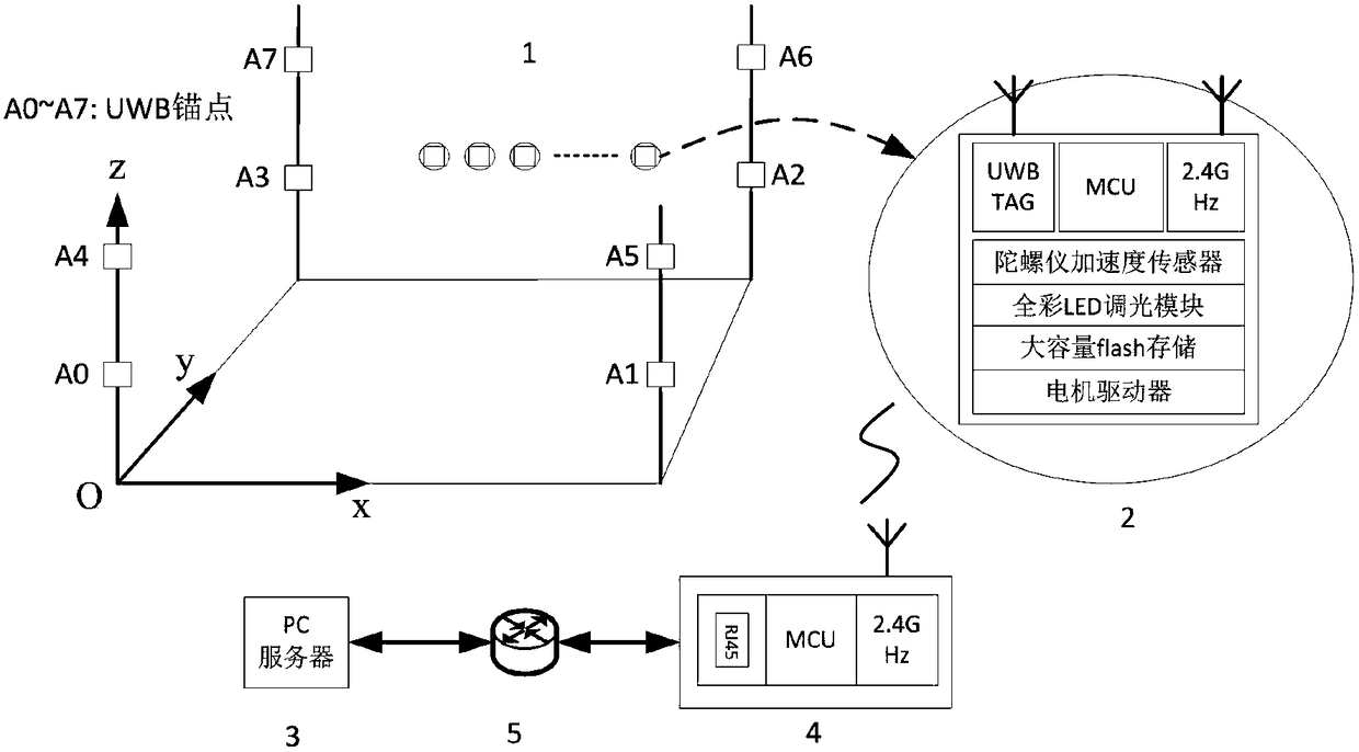
[0041] Such as figure 1 As shown, the UWB positioning-based UAV formation performance system embodiment is provided with a UWB three-dimensional positioning subsystem 1, a micro air vehicle subsystem 2, a formation navigation subsystem 3, a coordinator 4 and a router 5;

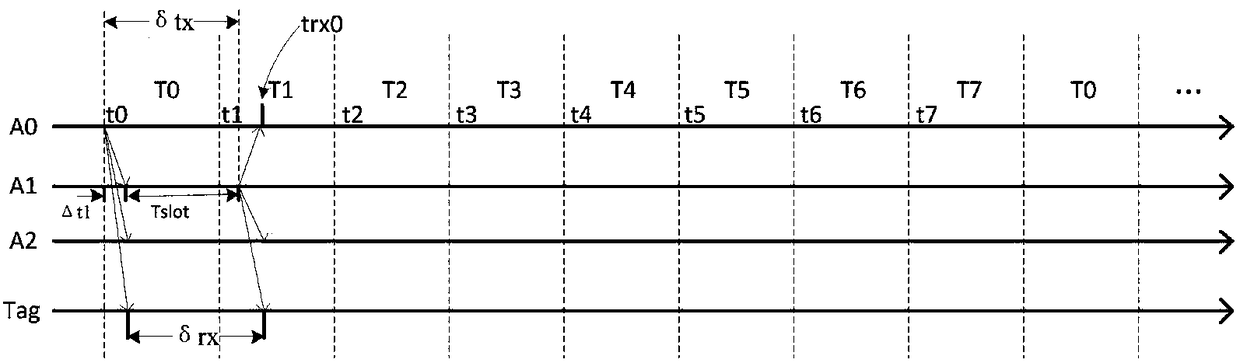
[0042] The UWB three-dimensional positioning subsystem 1 is composed of 8 positioning anchor points A1-A7 based on the ultra-wideband wireless transceiver module. T7 cyclically sends positioning signals;

[0043] The MAV subsystem is composed of Cortex M4MCU, gyroscope acceleration sensor, motor driver, UWBTag, 2.4GHz communication module, full-color LED dimming module and large-capacity flash memory;

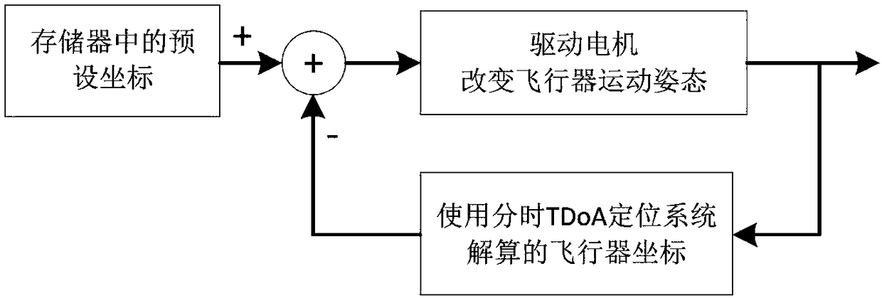
[0044] The formation navigation subsystem 3 simulates the flight pattern of the micro-aircraft cluster by computer, and adopts the distributed storage technology of the flight pattern;

[0045] Described co...


PUM


Abstract

The invention discloses an unmanned aerial vehicle formation performance system based on UWB location and an implementation method thereof. An ultra broadband wireless communication technology and a time division TDoA technology are utilized to establish a three-dimensional location system applied to indoor and outdoor small areas; varieties of technologies of micro quadcopter formation navigationflight technology, a full-color LED light dimming technology and the like are combined to be applied to an indoor / outdoor small area performance system. In a three-dimensional location area, an aircraft colony performing navigation flight according to planned tracks, and color change of dimmable LED lamps arranged on a plurality of micro aircrafts is controlled to construct varieties of static and dynamic flight patterns, and stronger visual effect can be generated. As the time division TDoA technology based on UWB, a computer simulation micro aircraft colony flight pattern technology, an unmanned aerial vehicle colony flight pattern distribution storage technology and a PC coordinator synchronization and self synchronization combined technology are utilized, price of the whole system canbe reduced.

Description

technical field [0001] The present invention relates to UAV formation performances, in particular to a UWB positioning-based UAV formation performance system and its implementation method that can work in indoor and outdoor small area UAV formation performances. Background technique [0002] The micro quadrocopter can freely realize hovering and free movement in space, and has great flexibility. It has the advantages of simple structure, good stability, low cost, and high cost performance. The application of quadcopters in consumer products is mainly concentrated in toys, model airplanes and aerial photography. With the rapid development of the field of micro UAVs, the direction of academic research has shifted to intelligent navigation based on quadcopters and formation control of multi-aircrafts. In the development of UAV technology, "cluster UAVs are the trend" has been recognized by the industry . [0003] In terms of specific applications, the use of drone fleets for ...

Claims


Application Information

Patent Timeline
Patent Type & Authority Applications(China)
IPC IPC(8): G05D1/10
CPCG05D1/104
Inventor 林和志李汉波石青洲章绍晨欧阳小敏沈平圳
Owner XIAMEN UNIV
Why Eureka
Try Eureka