Optical waveguide multimode to single mode transformer

a multi-mode, transformer technology, applied in the direction of instruments, semiconductor lasers, optical elements, etc., can solve the problems of high optical power density at the mirror of the laser, limited laser approach, mirror damage,

Inactive Publication Date: 2003-06-17
APPLIED WDM
View PDF13 Cites 109 Cited by
  • Summary
  • Abstract
  • Description
  • Claims
  • Application Information

AI Technical Summary

Problems solved by technology

This results in high optical power density at the mirror of the laser and consequently mirror damage.
This approach is limited in the number of lasers that can be practically operated at the same time, as well as by the finite spectral width of the pumping band of optical amplifiers.
It thus cannot operate in the lowest transverse mode.
However, a limitation of a broad area laser is the filamentary nature of the laser field, which in the absence of any mode stabilizing structure breaks up into filaments resulting in non-uniform optical power density across the mirror.
In fact coupling to a single mode fiber is not possible because of the multimode nature of broad area lasers.
It is known that suppression of filamentary operation results in significantly higher power output but mismatch between the mode of the laser and that of the optical fiber remains.

Method used


Image

  • Optical waveguide multimode to single mode transformer
  • Optical waveguide multimode to single mode transformer
  • Optical waveguide multimode to single mode transformer

Examples


Embodiment Construction

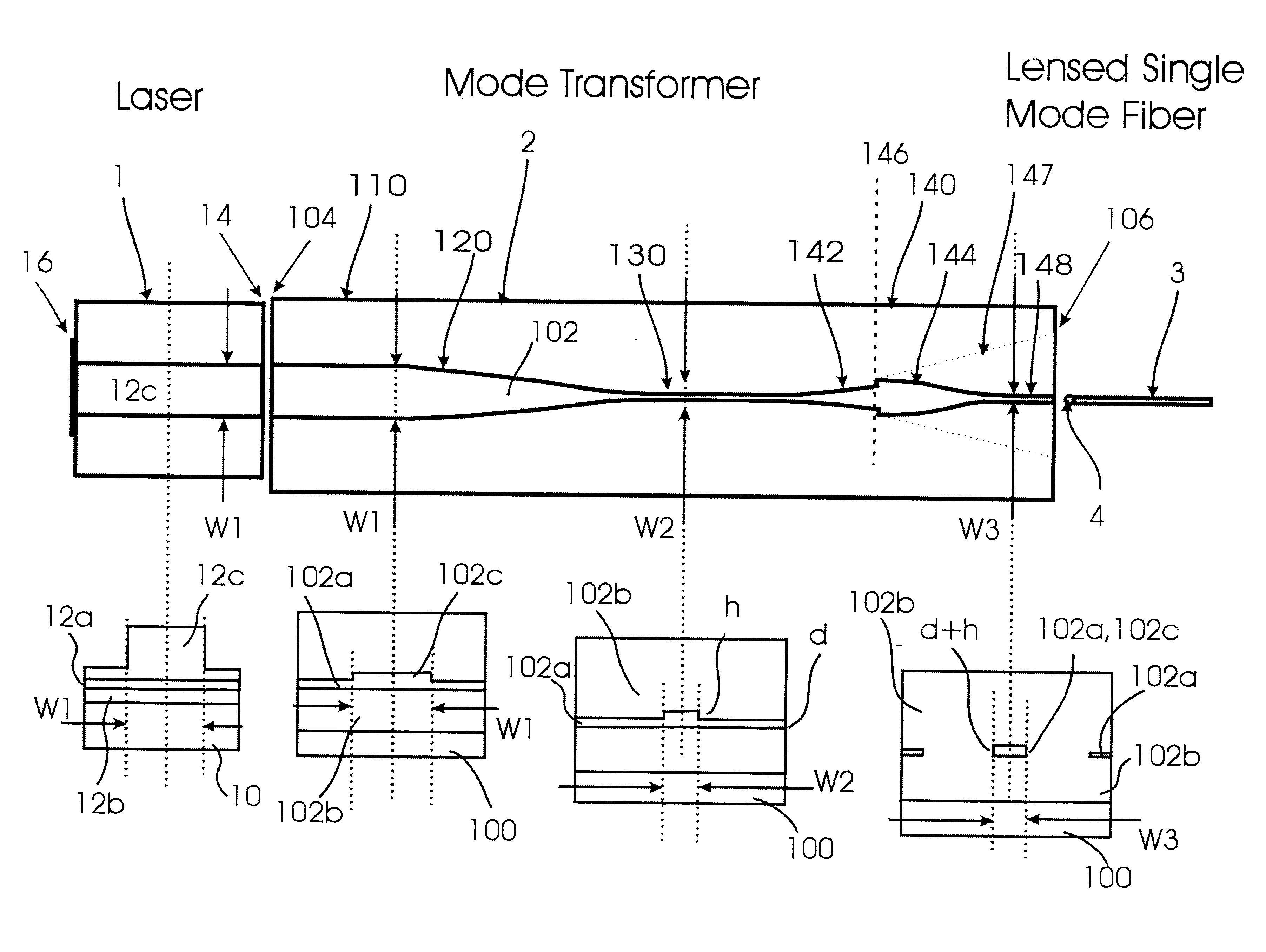
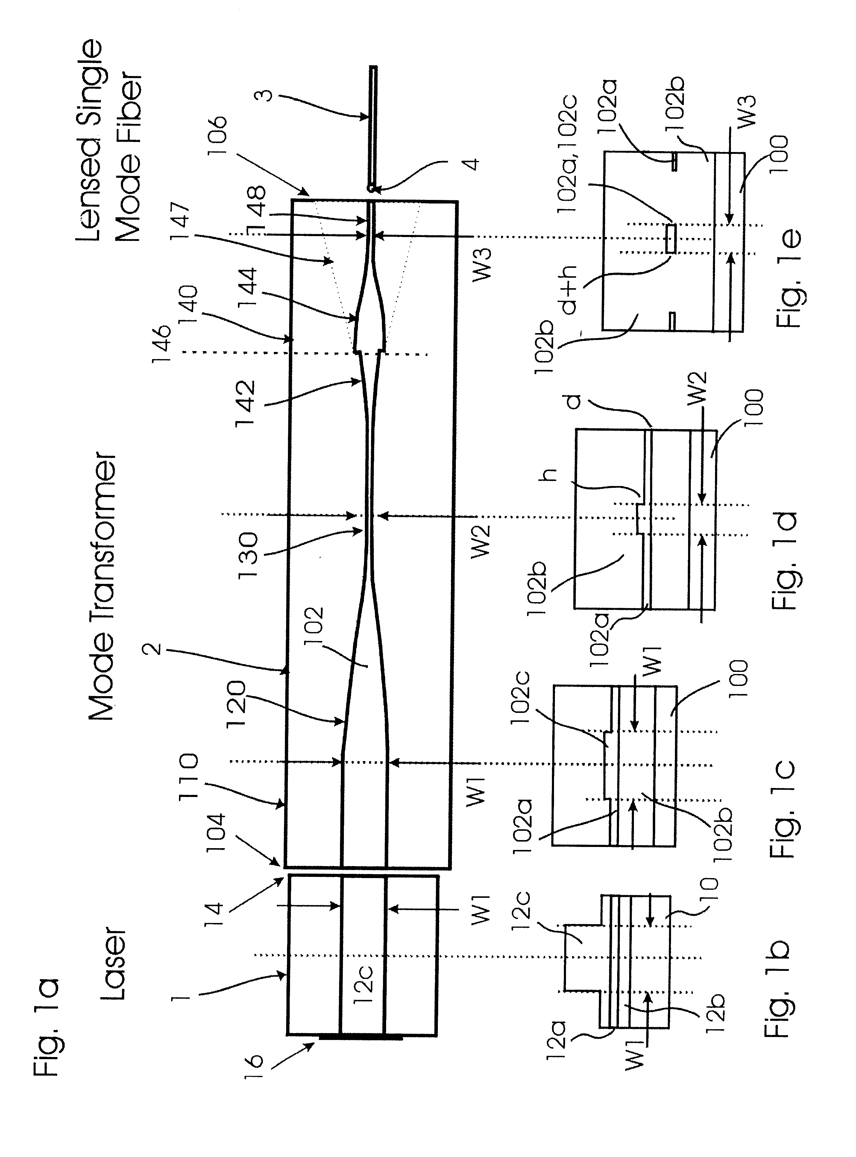
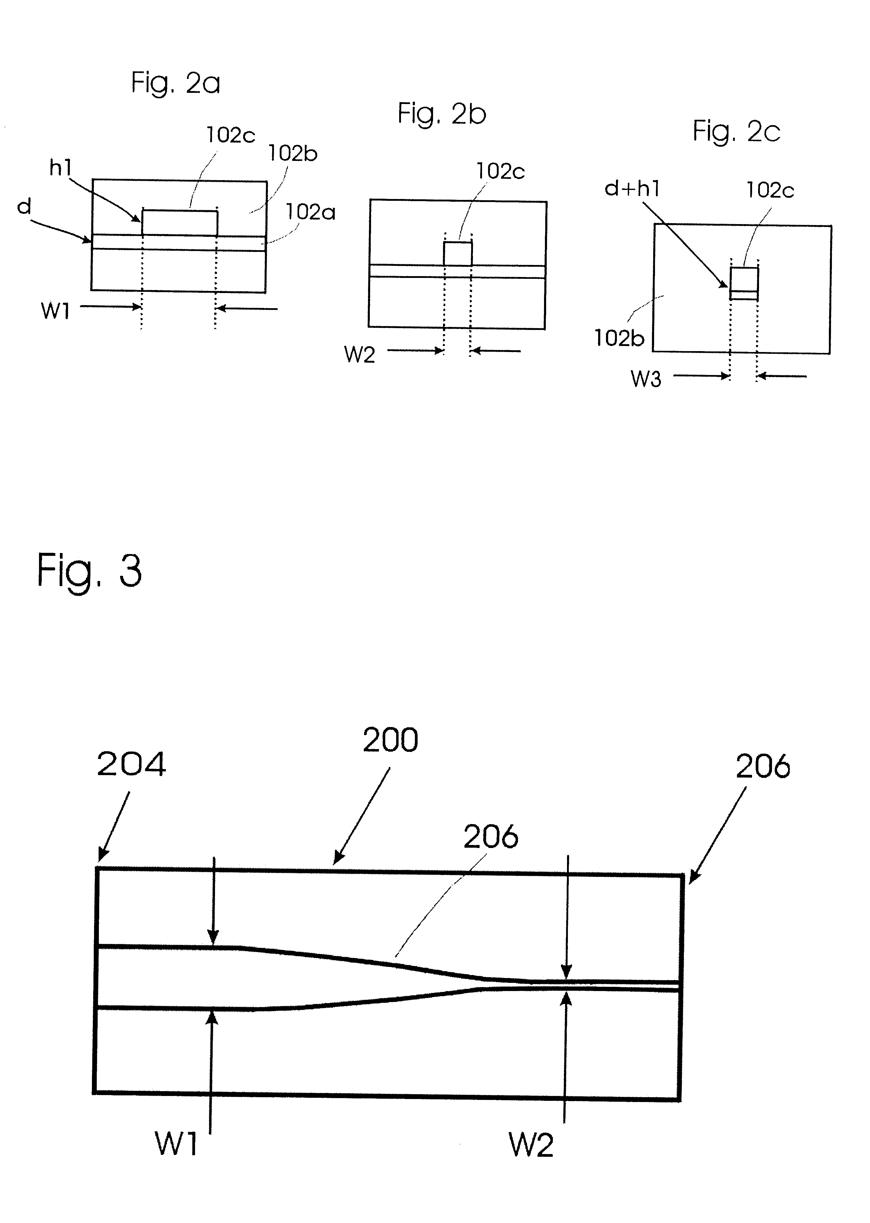
Throughout the specification and claims, references to "multimode" and "single mode" apply to the transverse (horizontal) dimension of the waveguide (unless otherwise stated); in a vertical dimension, it is assumed only a single (fundamental) mode is supported. In the vertical direction the peak power is always at the center of the waveguide. The output can be described as having a single lobe in the vertical direction, centered at the active region of the waveguide. In a single mode waveguide this will also be true in the horizontal direction. However, if the waveguide becomes wider, in the horizontal direction, other modes become possible. These may have, for instance, a minimum at the center of the waveguide between two symmetric maxima. There are small differences in wavelength between these two types of modes but the present invention is primarily concerned with spatial distributions of intensity.

FIG. 1a shows a top view of an optical waveguide mode transformer 2 designed to pr...


PUM


Abstract

An optical waveguide mode transformer has a substrate supporting a high refractive index core layer surrounded by lower refractive index cladding. The core layer includes a wide input waveguide section to accept a multimode, including a fundamental mode, light input. The input waveguide section is coupled to a narrow output waveguide section by a tapered region having a taper length enabling adiabatic transfer of the fundamental mode of the multimode light from the wide input waveguide section to the output waveguide section while suppressing(stripping) other modes of the multimode light input. The narrow output waveguide section supports a single mode light output comprising said fundamental mode. The core layer is contoured to include a localized upstanding ridge intermediate opposite lateral sides of the core layer. The output waveguide section includes a portion having a real index step between the core layer and cladding layers, and advantageously is functional to output a light beam having similar vertical and horizontal divergences.

Description

This invention relates to optical waveguide multimode to single mode transformers and to applications of such transformers in transferring optical signals from a laser to an optical fiber.BACKGROUND OF INVENTIONAdvances in optical amplifiers based on either erbium doped fiber or Raman amplification require increased power launched into a single mode optical fiber. Single mode lasers used as pumps for optical amplifiers can provide launched powers of approximately 200 mW at a wavelength of 980 nm. The requirement of single mode operation limits the width of the laser active layer to 3-4 microns. This results in high optical power density at the mirror of the laser and consequently mirror damage. Higher powers are provided by arrays of single mode pump lasers, with each laser operating at a slightly different wavelength. The different wavelengths can be combined into a single mode fiber using wavelength division multiplexing techniques. This approach is limited in the number of lasers...

Claims


Application Information

Patent Timeline
Patent Type & Authority Patents(United States)
IPC IPC(8): G02B6/125G02B6/14G02B6/42G02B6/12G02B6/122
CPCG02B6/12004G02B6/1228G02B6/125G02B6/14G02B6/4201H01S5/14H01S5/146G02B2006/12102G02B2006/12152G02B2006/12195H01S5/1014G02B6/4206
Inventor KAZARINOV, RUDOLF FEODORSTELMAKH, NIKOLAI MICHAELTEMKIN, HENRYK
Owner APPLIED WDM
Why Eureka
Try Eureka