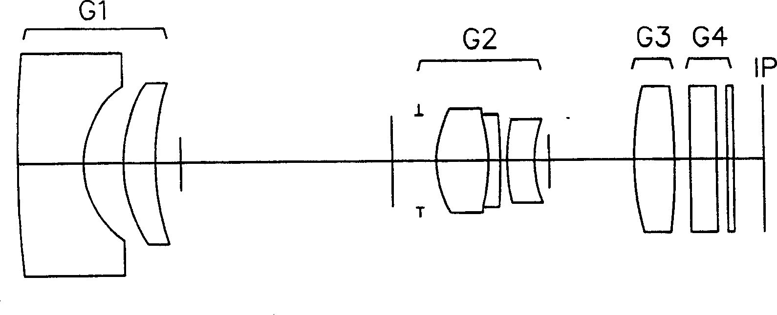
Lens group of zoom Lens
A zoom lens and lens group technology, applied in the field of lens groups, can solve the problems of not being able to see, too many lens books, unsatisfactory, etc., and achieve the effect of reducing the thickness on the axis and reducing the number of lenses
- Summary
- Abstract
- Description
- Claims
- Application Information
AI Technical Summary
Problems solved by technology
Method used
Image

Examples
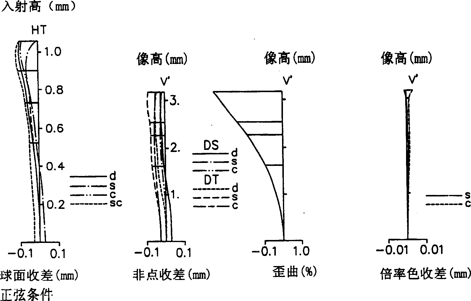
Embodiment 1
[0073] Focus distance: 6.050-17.443, F value: 2.8-4.6, picture angle: 59.2-21.5
[0074]
[0075] Focal distance 6.05 9.3 17.443
[0076] variable interval
[0077] D4 14.6 37.59 2.73
[0078] D10 5.47 8.166 18.6
[0079] D12 1 1.921 1.214
[0080] Aspheric coefficient
[0081] R2K: -0.50713
[0082] A: -0.12545e-3. B: 0.12513e-4, C: -0.14594e-5, D: 0.64259e-7, E: -0.12677e-8
[0083] R9 K: -4.0
[0084] A: -0.10000e-3, B: -0.14753e-3, C: 0.43244e-4, D: -0.73470e-5, E: 0.43533e-6
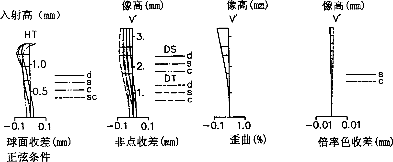
Embodiment 2
[0086] Focus distance: 6.026-17.403, F value: 2.9-5.2, picture angle: 62.4-22.7
[0087]
[0088] Focus distance 6.026 9.30 117.403
[0089] variable interval
[0090] D4 15.465 7.51 2.69
[0091] D10 5.5 7.377 17.852
[0092] D12 1 2.359 1.197
[0093] Aspheric coefficient
[0094] R2 K: -0.73635
[0095] A: 0.17323e-3, B: 0.19925e-4, C: -0.14204e-5, D: 0.59161e-7, E: -0.95709e-9
[0096] R9 K: -6.0
[0097] A: -0.10000e-4, B: -0.41925e-3, C: 0.16119e-4, D: -0.17371e-5, E: 0.21220e-6
Embodiment 3
[0099] Focus distance: 6.043-17.485, F value: 3.0-5.5, picture angle: 63.4-23.3
[0100]
[0101] Focus distance 6.043 9.3 17.485
[0102] variable interval
[0103] D4 13.418 6.891 2.73
[0104] D10 5.552 9.113 18.6
[0105] D12 1 1.197 1.178
[0106] Aspheric coefficient
[0107] R2K: -0.73984
[0108] A: 0.17591e-3, B: 0.23166e-4, C: -0.19438e-5, D: 0.91107e-7, E: -0.16429e-8
[0109] R9 K: -6.0
[0110] A: 0.00000e+00, B: -0.44014e-4, C: -0.48368e-5, D: 0.46377e-6, E: 0.00000e+00
PUM
 Abstract
Description
Claims
Application Information
PatSnap Eureka turns technology decisions into work you can execute. Powered by our Innovation Knowledge Graph, it runs expert workflows across engineering, life sciences, materials and intellectual property. Get your review-ready output in minutes.


