
Lens group of zoom Lens

A zoom lens and lens group technology, applied in the field of lens groups, can solve the problems of invisibility, too many lens books, reduction, etc., and achieve the effect of reducing the number of lenses and reducing the thickness on the axis

Inactive Publication Date: 2005-03-30
LARGAN PRECISION
View PDF3 Cites 3 Cited by
  • Summary
  • Abstract
  • Description
  • Claims
  • Application Information

AI Technical Summary

Problems solved by technology

[0007] In addition, Japanese Patent Publication No.: JP 2000-8911, its first group lens is composed of three pieces of negative, negative and positive, and the second group of lenses is composed of three pieces of positive, negative and positive. There is a certain reduction effect, but the outer diameter and decentering characteristics of the front lens element have not improved but worsened
[0008] Equally, Japanese Patent Publication No.: No. 2001-318311, its first group lens is negative, negative, positive three-piece formation, and the second group lens is positive, cemented (positive, negative) three-piece formation; Although, The reduction of the total optical length and the decentering sensitivity in the second group lens are improved, but the outer diameter of the front element is not improved at all.
[0009] In addition, with the Japanese Patent Publication No.: JP 2001-281545, it proposes that the first group of lenses is composed of negative and positive two pieces, and the second group of lenses is positive and negative bonding and negative and positive bonding Composed of four lenses, although the slenderness of the first group of lenses has a certain effect on the reduction of the outer diameter and optical length of the front lens, but the lens book of the second group of lenses is still too much and not satisfactory.

Method used

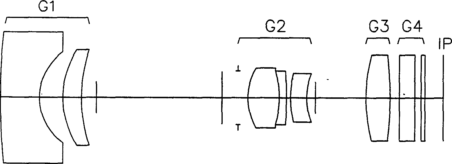
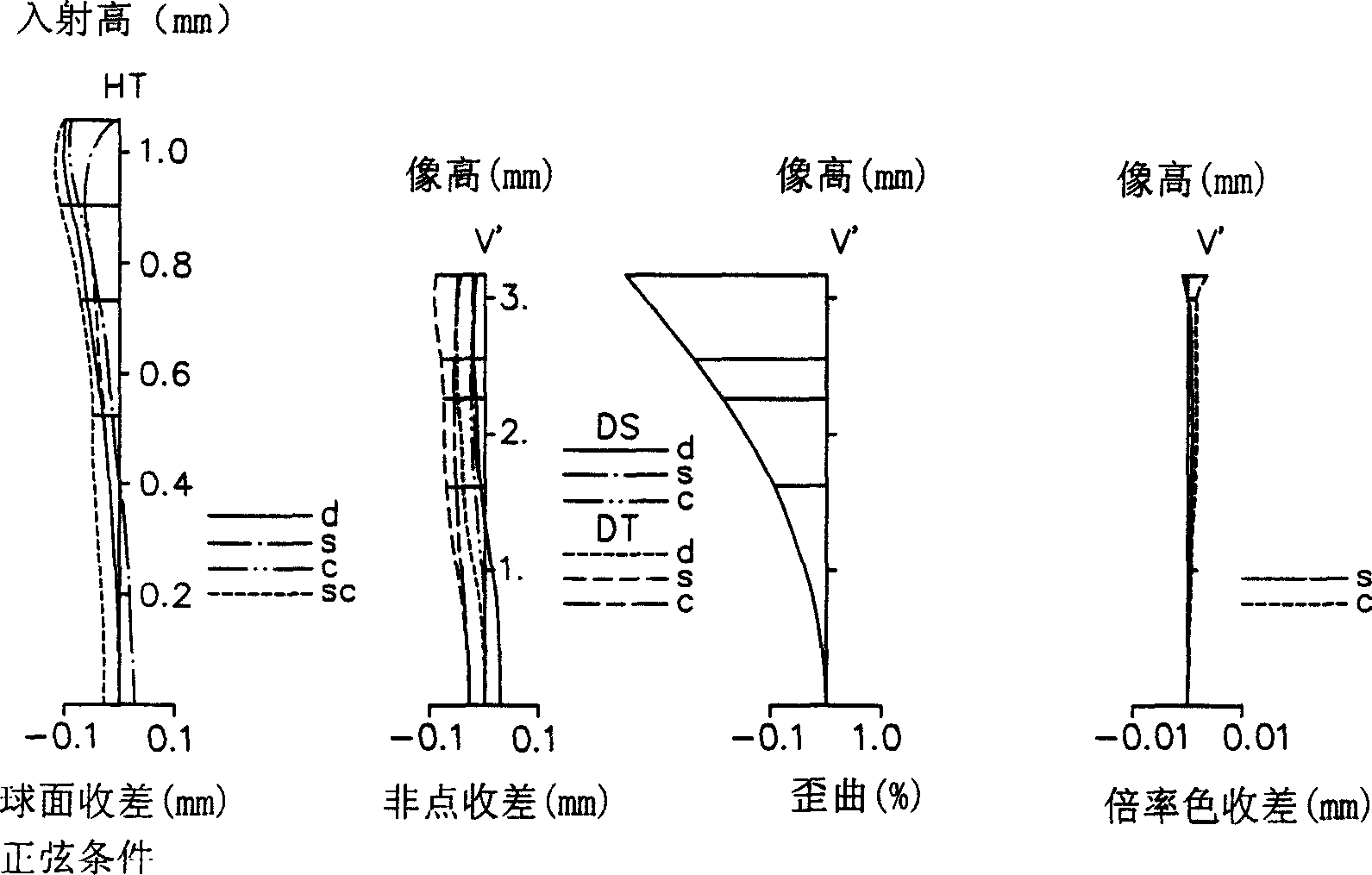
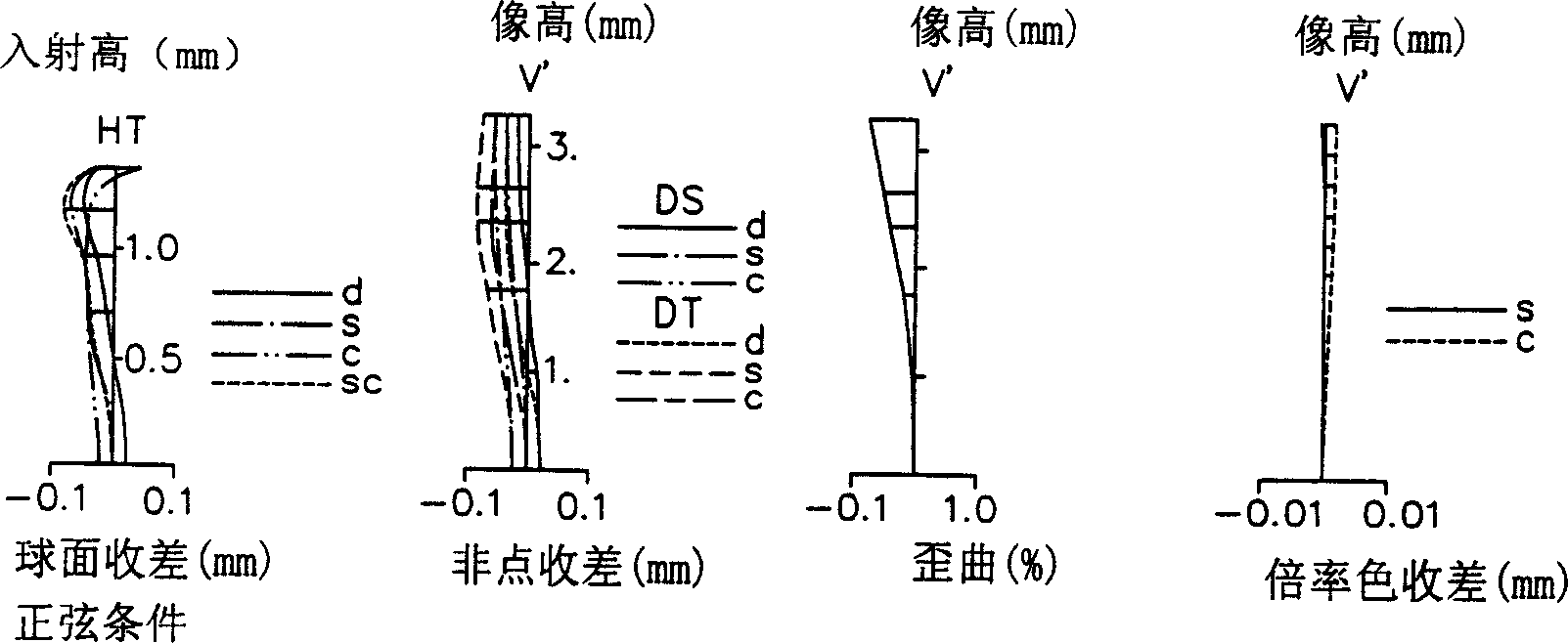

Image

  • Lens group of zoom Lens
  • Lens group of zoom Lens
  • Lens group of zoom Lens

Examples


Embodiment 1

[0073] Focus distance: 6.050-17.443, F value: 2.8-4.6, picture angle: 59.2-21.5

[0074]

[0075] Focal distance 6.05 9.3 17.443

variable interval

D4 14.63 7.59 2.73

D10 5.47 8.166 18.6

D12 1 1.921 1.214

[0076] Aspheric coefficient

[0077] R2K: -0.50713

[0078] A: -0.12545e-3, B: 0.12513e-4, C: -0.14594e-5, D: 0.64259e-7, E: -0.12677e-8

[0079] R9 K: -4.0

[0080] A: -0.10000e-3, B: -0.14753e-3, C: 0.43244e-4, D: -0.73470e-5, E: 0.43533e-6

Embodiment 2

[0082] Focus distance: 6.026-17.403, F value: 2.9-5.2, picture angle: 62.4-22.7

[0083]

[0084] Focal distance 6.026 9.301 17.403

variable interval

D4 15.465 7.51 2.69

D10 5.5 7.377 17.852

D12 1 2.359 1.197

[0085] Aspheric coefficient

[0086] R2 K: -0.73635

[0087] A: 0.17323e-3, B: 0.19925e-4, C: -0.14204e-5, D: 0.59161e-7, E: -0.95709e-9

[0088] R9 K: -6.0

[0089] A: -0.10000e-4, B: -0.41925e-3, C: 0.16119e-4, D: -0.17371e-5, E: 0.21220e-6

Embodiment 3

[0091] Focus distance: 6.043-17.485, F value: 3.0-5.5, picture angle: 63.4-23.3

[0092]

[0093] Focus distance 6.043 9.3 17.485

Variable Interval D4 13.418 6.891 2.73

D10 5.552 9.113 18.6

D12 1 1.197 1.178

[0094] Aspheric coefficient

[0095] R2K: -0.73984

[0096] A: 0.17591e-3, B: 0.23166e-4, C: -0.19438e-5, D: 0.91107e-7, E: -0.16429e-8

[0097] R9 K: -6.0

[0098] A: 0.00000e+00, B: -0.44014e-4, C: -0.48368e-5, D: 0.46377e-6, E: 0.00000e+00


PUM


Abstract

The invention includes first group of lenses with negative meandering force. second group of lenses with positive meandering force and third group of lenses with positive meandering force successively; at the time of that from wide-angle double to looking far into the distance the interval between first group of lenses and second group of lenses can be reduced, and the interval between second group of lenses and third group of lenses can be widened. Said invention is characterized by that said first group of lenses contains negative meniscus lens whose convex surface is faced with side of body and positive meniscus lens whose convex surface is faced with side of body, said second group of lenses contains positive meanderingly-bonded lens and negative meniscus lens whose convex surface is faced with body which are arranged successively form objective side direction, and the third group of lenses is a double-convex lens.

Description

technical field [0001] The invention relates to photosensitive coupling elements used in video cameras and digital camera photographic equipment, in particular to a zoom lens lens group. Background technique [0002] Recently, the solid-state imaging elements used in video cameras and digital cameras, etc., are required to be high-performance products for the lens series used with the high density of imaging elements and the miniaturization of pixel size. At the same time, for the sake of convenience and portability , hopefully a simpler lens or a lens for a zoom lens. [0003] This kind of camera or silver-salt coating camera uses different lens series. For the imaging surface, if there is not enough vertical incidence of the chief ray of the light beam facing various image heights, then from the structure of the camera element According to the characteristics of the lens alone, the formation of the efficiency coefficient of the CCD will cause low ambient illumination, as ...

Claims


Application Information

Patent Timeline
Patent Type & Authority Applications(China)
IPC IPC(8): G02B13/18G02B15/14
Inventor 陈俊杉
Owner LARGAN PRECISION
Learn More