Elevator main rope elongation compensating apparatus
A compensating device and elevator technology, applied in elevators, lifting equipment in mines, transportation and packaging, etc., can solve the problem of time-consuming measurement and adjustment work
- Summary
- Abstract
- Description
- Claims
- Application Information
AI Technical Summary
Problems solved by technology
Method used
Image
Examples
Embodiment 1
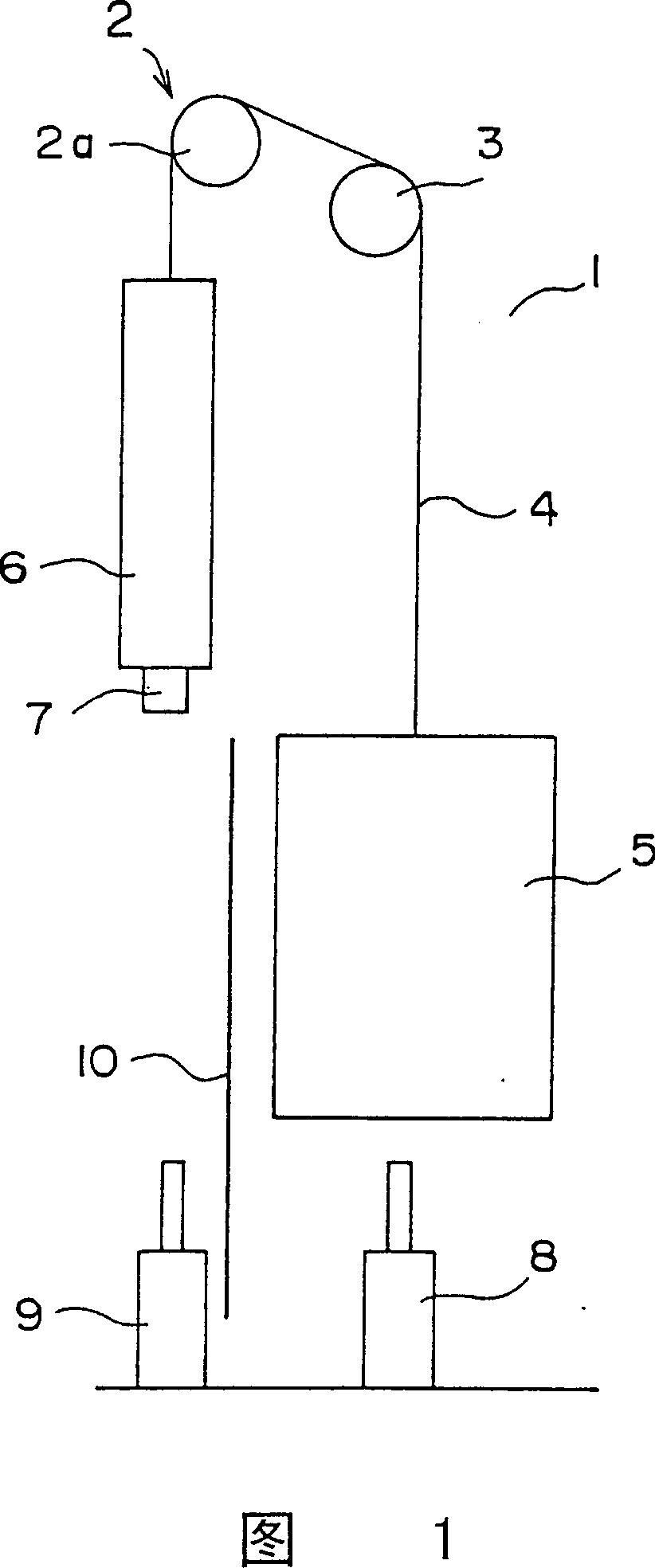
[0025] Fig. 1 is a general schematic diagram showing an elevator apparatus according to Embodiment 1 of the present invention. In this figure, a hoist 2 and a deflecting pulley 3 are arranged in the upper part of an elevator shaft 1. The hoist 2 has a driving pulley 2a. A plurality of main ropes 4 pass around the driving pulley 2a and the deflection pulley 3.
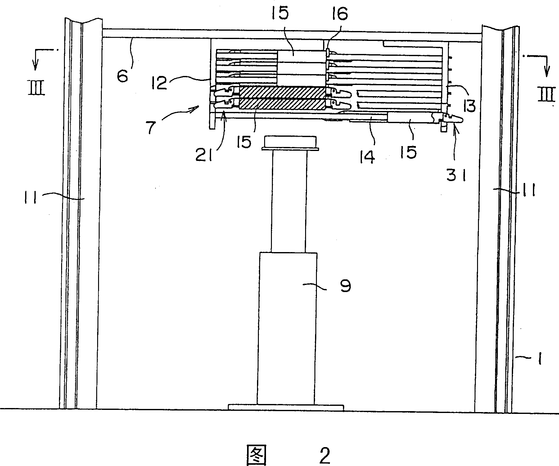
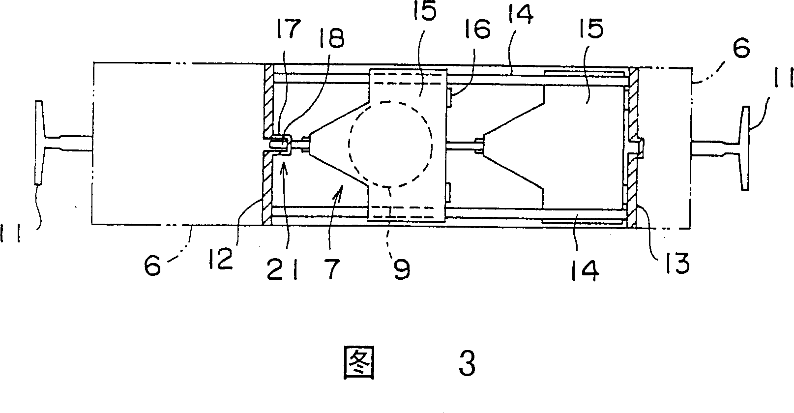
[0026] At the first end of the main rope 4, an elevator car 5 is suspended. A counterweight 6 is hung on the second end of the main rope 4. An extension part 7 of a main rope elongation compensation device for compensating for the main rope elongation is installed to the lower part of the counterweight 6. The extension part 7 protrudes downward from the lower part of the counterweight 6.
[0027] An elevator car buffer 8 is installed under the elevator car 5 at the bottom of the elevator shaft 1. A counterweight buffer 9 and a protective screen 10 are installed in the lower part of the elevator shaft 1 under the counterweig...
Embodiment 2
[0042]Fig. 5 is a partial cross-sectional view showing a partial cross-sectional view of an elevator main rope extension compensation device according to Embodiment 2 of the present invention; Fig. 6 is a partial cross-sectional view taken along the line "VI-VI" of Fig. 5; and 7 is an enlarged cross-sectional view showing a part of FIG. 5.
[0043] In these figures, the extension 7 also includes compression springs 22, each of which functions as a pressure-applying structure that forces a movable partition to move to a non-contact position. The compression spring 22 is provided between the first support bracket 12 and the movable partition 15. The compression spring 22 is a coil spring, and the guide rod 14 is inserted and passed through the inside thereof. When the locked state held by a contact position locking mechanism 21 is released, the corresponding movable partition 15 is pressurized by the compression spring 22 and automatically moves to the non-contact position.
[0044]...
Embodiment 3
[0052] Fig. 8 is a cross-sectional view showing a part of a main rope elongation compensation device according to Embodiment 3 of the present invention. In this figure, a detection switch 28 as a part of a lock release detector is mounted on the mounting member 23. When the release lever 25 is pivoted to the second position (two-dot chain line in the figure), the detection switch 28 is driven to output a detection signal. Here, a micro switch is used as the detection switch 28.
[0053] A main rope elongation compensation device according to Embodiment 3 includes an extension part 7, a lock release mechanism 27 and a detection switch 28. The rest of the lock release mechanism is similar to that of the second embodiment.
[0054] In this type of main rope extension compensation device, when the release lever 25 is pivoted from the first position to the second position, the detection switch 28 is driven to output a detection signal. Therefore, the locked state held by a contact posi...
PUM
 Abstract
Description
Claims
Application Information
 - R&D Engineer
- R&D Manager
- IP Professional
- Industry Leading Data Capabilities
- Powerful AI technology
- Patent DNA Extraction
Browse by: Latest US Patents, China's latest patents, Technical Efficacy Thesaurus, Application Domain, Technology Topic, Popular Technical Reports.
© 2024 PatSnap. All rights reserved.Legal|Privacy policy|Modern Slavery Act Transparency Statement|Sitemap|About US| Contact US: help@patsnap.com


