Electronic control nailer

A nailing gun and control technology, applied in the field of nailing guns, can solve the problems of uneven nail distance, difficult control, and inability to control the position of the nail distance.

Inactive Publication Date: 2007-04-18
张文州
View PDF3 Cites 4 Cited by
  • Summary
  • Abstract
  • Description
  • Claims
  • Application Information

AI Technical Summary

Problems solved by technology

[0004] 1. When you want to fire continuously, you must continue to press the trigger switch, and then drive the loose mouth of the gun body to press down toward the bottom of the safety lever group in a continuous jumping manner, so as to achieve continuous firing; in this way, it not only It is not easy to get accurate control due to the way of jumping and continuous firing. At the same time, it is also impossible to effectively control the gun nozzle to aim at the object, and it is easy to cause the accidental danger of nails nailing the user after firing.
[0005] 2. As mentioned in the previous item, it cannot control the position of the nail distance after continuous firing, which will cause uneven nail distance
[0007] 4. Since the safety lever group and the trigger switch are located on the outside of the gun body, the change of its overall shape is quite limited, and the shape is single

Method used


Image

  • Electronic control nailer
  • Electronic control nailer
  • Electronic control nailer

Examples


Embodiment Construction

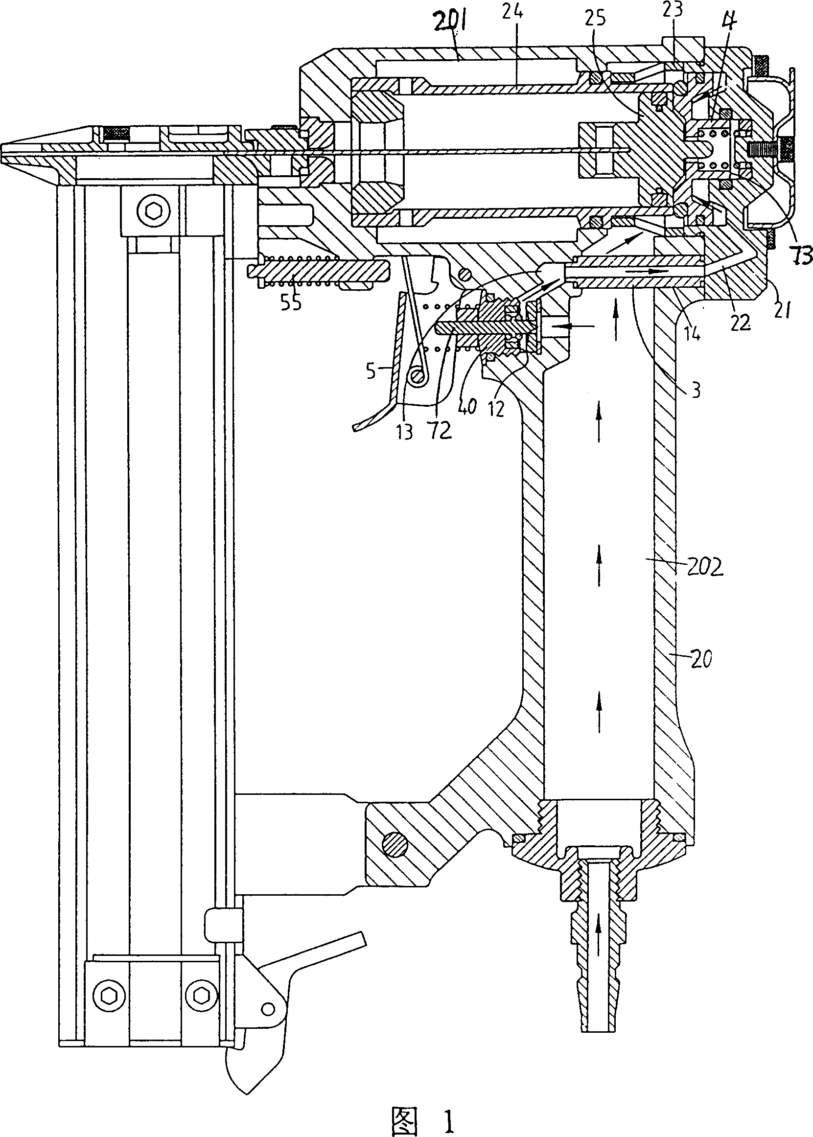
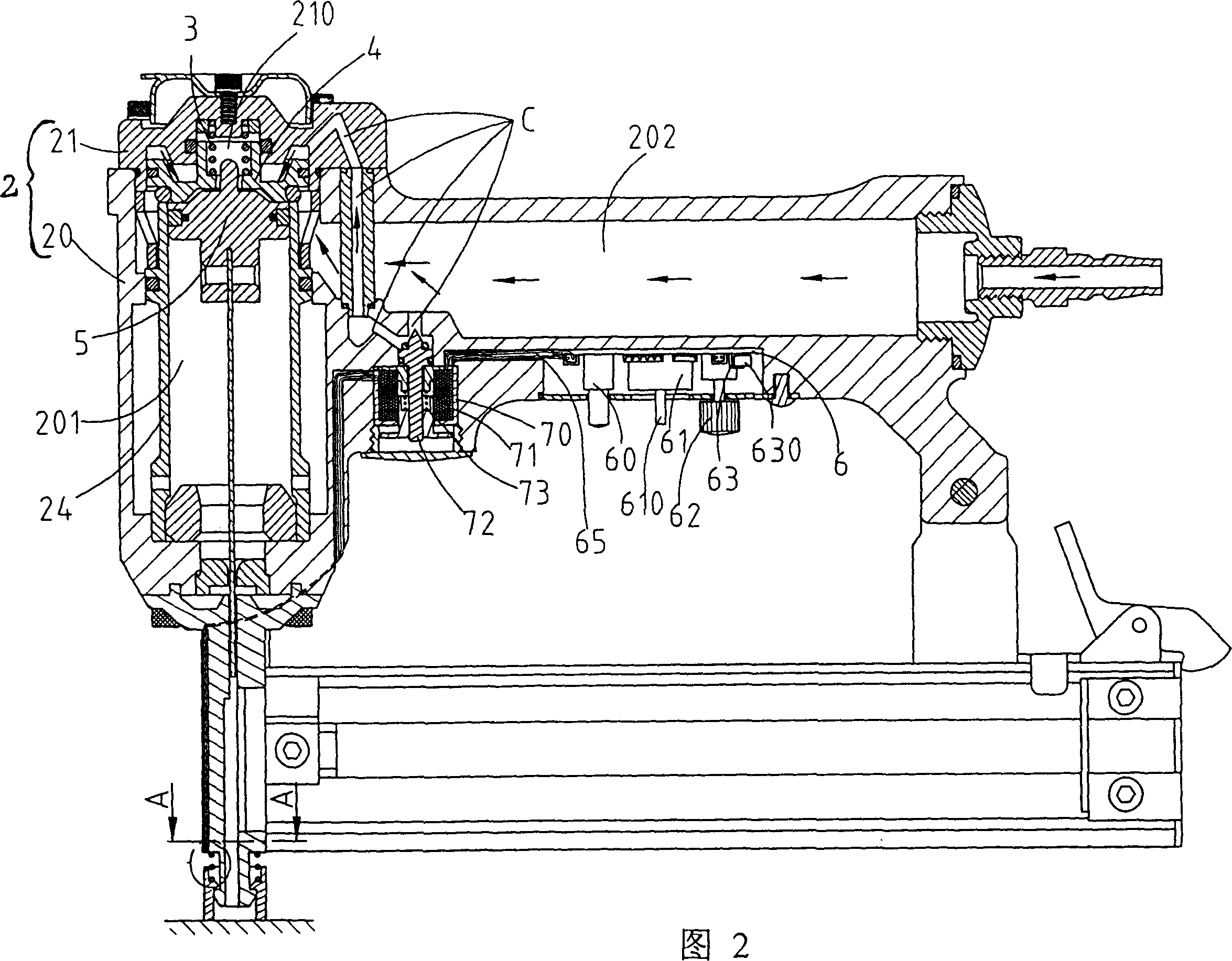
[0027] As shown in Fig. 2, Fig. 3, Fig. 4 and Fig. 5, the present invention includes a gun body group 2, wherein the gun body group 2 is made up of a gun body 20 and an upper cover 21, and the gas in the gun body 20 The chamber 201 and the accommodating part 210 of the upper cover 21 accommodate the elastic body 3, the pressing seat 4 and the piston body 5 in sequence; and the gun body group 2 can form a main air passage 202 and an upper air passage C , and the main airway 202 and the upper airway C communicate with the air chamber 201 of the gun body 20 and the accommodating portion 210 of the upper cover 21 respectively, and make one end of the main airway 202 and one end of the upper airway C respectively located The bottom and top of the top pressure seat 4; again, the appropriate positions of the gun body group 2 are respectively provided with a control circuit board 6, a solenoid valve group and a sensing component 8, and the control circuit board 6, the solenoid valve gr...


PUM


Abstract

An electronically controlled nailing gun is composed of a gun body unit consisting of gun body and top cover, the elastic body, pushing unit and piston contained in the air chamber of gun body and the cavity of top cover, primary air channel, upper air channel, the control circuit board with key switch, switching switch, adjustable pulse switch and battery holder, electromagnetic valve set and contact sensor.

Description

technical field [0001] The invention relates to a nailing gun, in particular to an electronically controlled nailing gun. Background technique [0002] At present, the structure of commonly used nailing guns, as shown in Figure 1, is mainly to pivotally arrange the upper cover 21 above the air chamber 201 of the gun body 20 by means of a locking piece, and to make the upper cover 21 and the gun body 20 air A spring 73, a top pressure seat 4, a cylinder seat cover 23 and a cylinder seat 24 are sequentially arranged between the chambers 201, and the piston group 25 can be moved up and down at the inner edge of the hollow cylinder seat 24, and, Appropriate places in the gun body 20 are respectively provided with an air chamber 201, a main air passage 202, an accommodating chamber 12, a guide hole 13 and a perforation 14, wherein the main air passage 202 communicates with the air chamber 201 and the accommodating chamber 12 respectively. , and the accommodating chamber 12 commu...

Claims


Application Information

Patent Timeline
Patent Type & Authority Patents(China)
IPC IPC(8): B25C1/06
Inventor 张文州
Owner 张文州
Why Eureka
Try Eureka