Separable bottom stopper for zipper

A stopper, disengagement technology, applied in the direction of sliding fastener components, applications, fasteners, etc., can solve the problems of not having raised locking claws, not being able to be replaced by reverse sliding parts, and unable to hold sliding parts stably, etc. Achieve smooth opening/closing operation

Inactive Publication Date: 2002-05-29
YKK CORP
View PDF2 Cites 4 Cited by
  • Summary
  • Abstract
  • Description
  • Claims
  • Application Information

AI Technical Summary

Problems solved by technology

Therefore, it cannot be used to replace the reverse opening type disengageable bottom end stop of the card box 2" with a reverse slide
That is to say, this disengageable bottom end stopper cannot stably hold the slider placed at one end o

Method used


Image

  • Separable bottom stopper for zipper
  • Separable bottom stopper for zipper
  • Separable bottom stopper for zipper

Examples


Embodiment Construction

[0035] Hereinafter, preferred embodiments of the releasable bottom end stopper for a slide fastener of the present invention will be described with reference to the accompanying drawings.

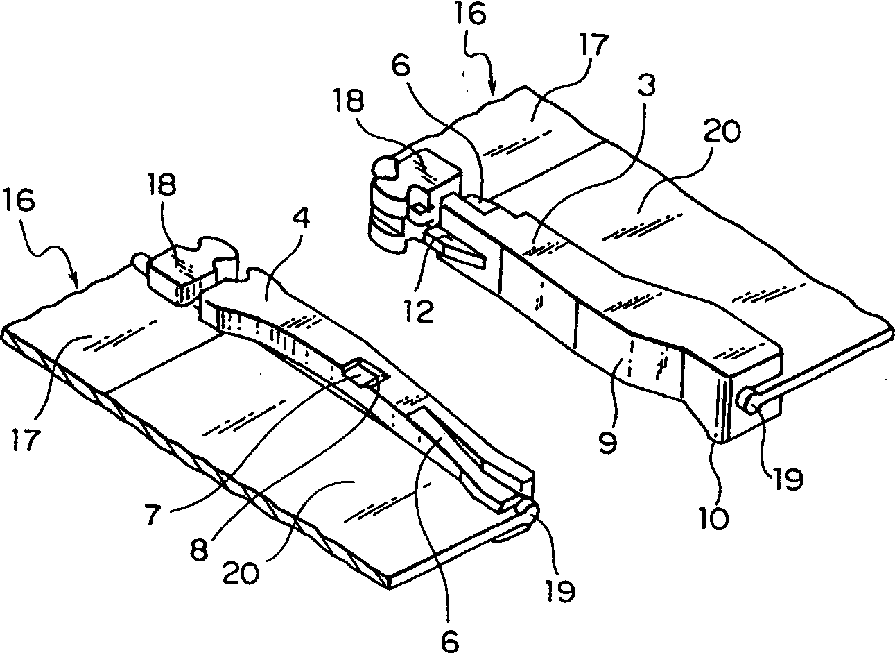
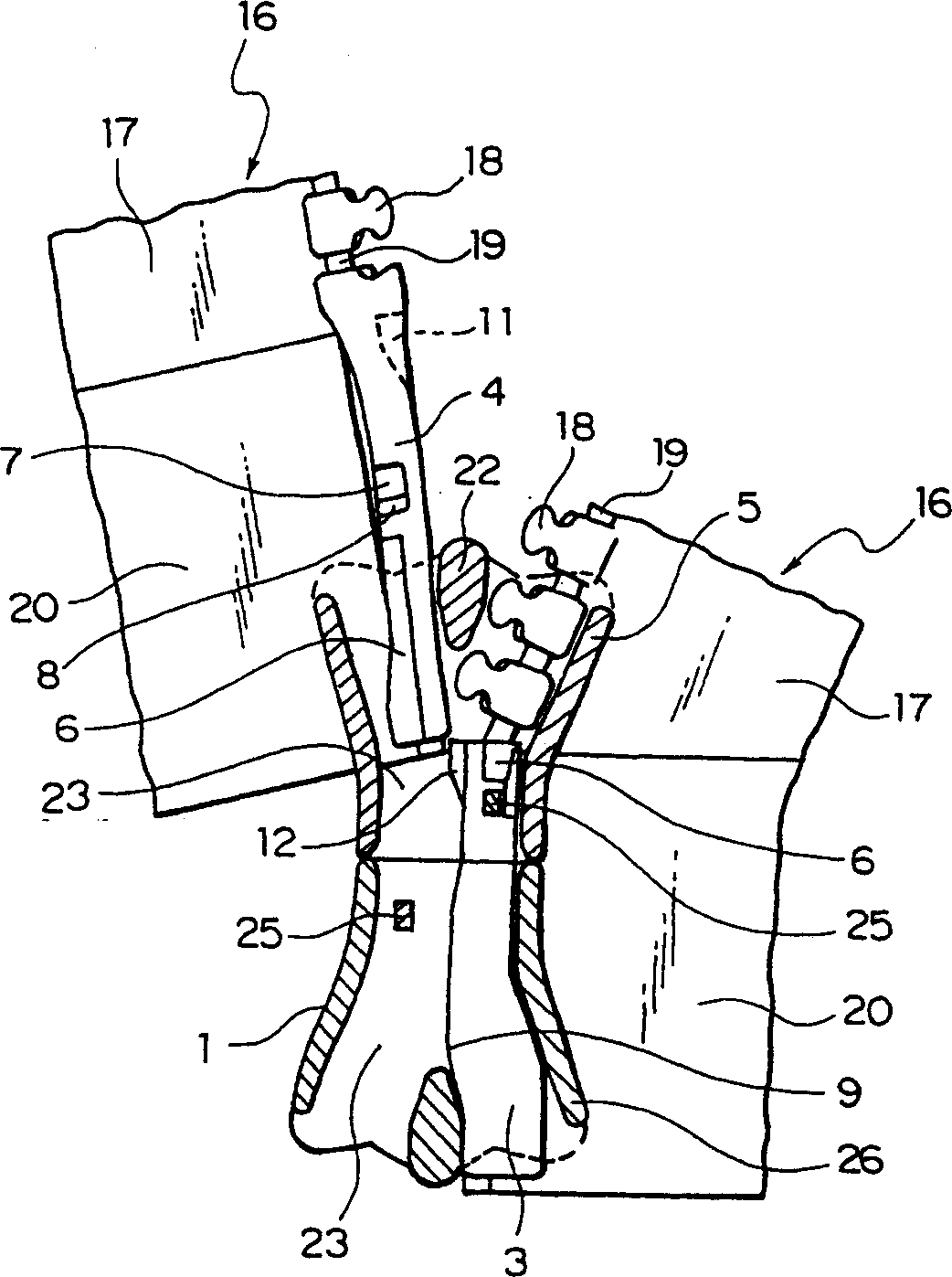
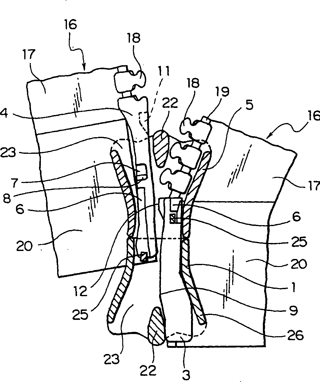
[0036] A first embodiment of the disengageable bottom end stop of the present invention is Figure 1 to Figure 4 As shown, the disengageable bottom end stopper for zippers of the present invention includes three components: a reverse opening slide 1 , a female insert 3 and a male insert 4 . The slide 5 for opening / closing the joint chain 15 is inserted into the reverse opening slide 1 through the joint chain 15 . In the reverse opening slider 1 and slider 5, such as Figure 6 As shown, the body 21 is molded by die-casting from a metal such as zinc alloy and aluminum alloy, wherein an upper plate 27 and a lower plate 28 arranged parallel to each other are connected by the ends of their rhomboids 22 . A cover 24 having a protruding locking pawl 25 at one side made by pressing a metal plate ...


PUM


Abstract

This invention provides a releasable bottom end stop for slide fastener which allows an insert pin thereof to be operated smoothly on being inserted into a semiautomatic/automatic stop slider. A slope for raising a locking pawl of an automatic or a semi-automatic stop mechanism provided on a slider when the insert pin is inserted into an inverse-opening type slider or an ordinary slider is provided obliquely so as to extend from a front end of the surface of an insert pin to a proximal end thereof. Additionally, a concave portion whose inlet is inclined for holding the locking pawl is provided over this slope. The inverse-opening slider is fitted in a stringer on a box pin side and another slider is also fitted such that it comes into contact with a top of the inverse-opening slider. If the insert pin disposed on another stringer is inserted with this condition, the locking pawl is raised by the slope so that the insert pin can be inserted smoothly and held in a stable condition.

Description

technical field [0001] The present invention relates to a detachable bottom end stopper for a zipper, and more particularly to a detachable bottom end part, which is characterized in that it comprises a box, a female and a male Disengageable bottom end stops, or releasable bottom stops of the reverse opening type comprising a reverse opening slide, a female insert and a male insert, wherein the male insert is modified so that Smooth disengagement and engagement operations are obtained. Background technique [0002] Among the conventional disengageable bottom end stoppers, Japanese Utility Model Patent Publication No. 63-31607 discloses a disengageable bottom end stopper, such as Figure 11 Shown, the inner edge of an end portion on an engaging element 18' side of the female inserter 3', that is to say, an edge portion of the female inserter 3' on the engaging strip side is cut off, thereby being beveled The shape of a slope 6'. [0003] In addition, in a disengageable bott...

Claims


Application Information

Patent Timeline
IPC IPC(8): A44B19/24A44B19/00A44B19/38
CPCA44B19/388Y10T24/2513Y10T24/2516Y10T24/2593Y10T24/2595A44B19/00
Inventor 高泽成吉松本敏
Owner YKK CORP
Why Eureka
Try Eureka