Reel pedestal for fishing rod and fishing rod

A technology for reels and fishing rods, applied in fishing rods, applications, fishing, etc., can solve the problems of fishing rod posture instability, ring finger and little finger pain, not long enough, etc., to achieve the effect of easy casting, sufficient grip, and easy control

Inactive Publication Date: 2002-07-10
FUJI IND
View PDF3 Cites 3 Cited by
  • Summary
  • Abstract
  • Description
  • Claims
  • Application Information

AI Technical Summary

Problems solved by technology

Because holding the rod usually takes a long time until the fish is hooked, it causes pain comparable to that of the ring finger and little finger
[0026] In addition, since only one finger can be hooked on the conventional trigger f, in order to stably maintain the posture in the direction of rotation of the axis of the fishing rod, a certain degree of force must be exerted to hold the fishing rod.
That is to say, when using this kind of fishing rod, because the heavier reel will do various actions with the posture of turning to the top of the fishing rod or to the side, the fishing rod will also act on the rotating force in the direction of the shaft rotation, causing the fishing rod The posture of the fish is unstable, so the fisherman must often stop the rotation of the fishing rod caused by the rotational force
At this time, the distance D (refer to 14 (A)) between the finger hooked on the trigger and the thumb fingertip hooked on the reel c is not long enough for the existing trigger f, so it is necessary to To hold a fishing rod with some degree of strength to stop the rod from spinning

Method used


Image

  • Reel pedestal for fishing rod and fishing rod
  • Reel pedestal for fishing rod and fishing rod
  • Reel pedestal for fishing rod and fishing rod

Examples


no. 2 example

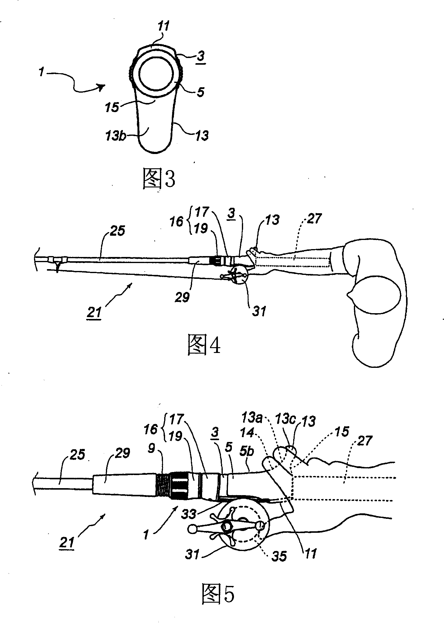
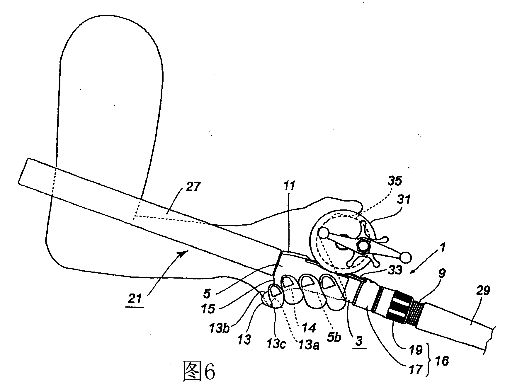
[0104] Also, according to such a grip, since the trigger 13 does not need to be clamped between the fingers, pain of the fingers can be avoided. [2. The second embodiment] (Fig. 7, Fig. 8)

[0105] 7 and 8 show a fishing rod reel holder 1A of a second embodiment. The difference between the reel stand 1A and the reel stand 1 of the first embodiment mainly lies in the inclination of the trigger. Therefore, only the differences will be described here, and for the remaining parts, the descriptions will be omitted by assigning the same symbols or plus ' to the parts in the diagram as those attached to the same parts in the reel seat. .

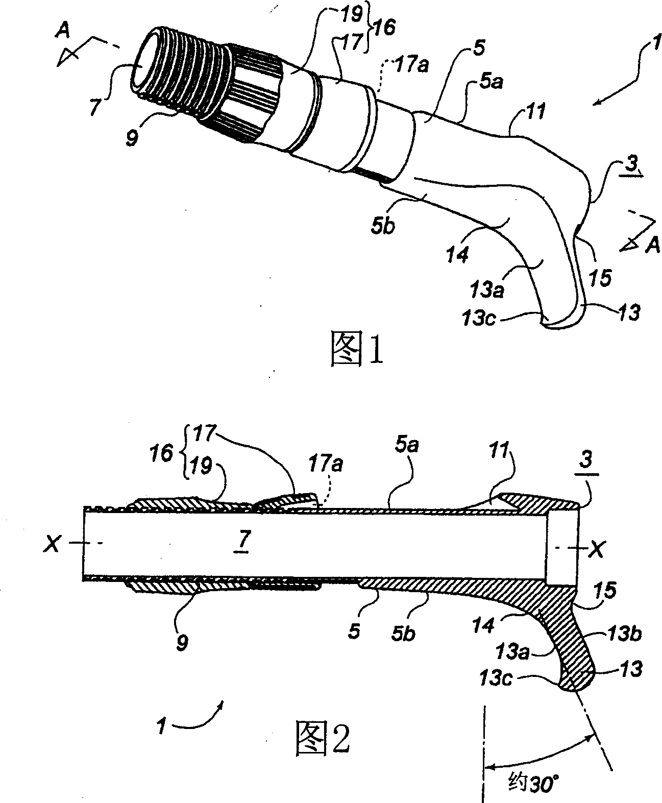
[0106] The form of the trigger 13' in this reel seat 1A is mainly suitable for a fishing rod for rock fishing, and its inclination (referring to the angle of the back and down in the direction perpendicular to the central axis X-X of the main body part 3) is due to the following The reason for this is about 50° which is slightly larger than the ...


PUM


Abstract

A reel foot placing seat and a rod are provided. A reel foot placing seat formed on a top portion of a circumferential surface of a body and a trigger protruding in a direction which is inclined in a backward-downward direction at approximately 30 DEG , are provided on the circumferential surface of the body. A length of the portion crossing over a connection portion that connects a lower portion of the body to a front surface of this trigger is such that a user can place two fingers can be placed thereon. The user's two fingers placed thereon are aligned in a direction in which the angle is opened with respect to a direction perpendicular to a center axis X-X of a fishing body. Therefore, without a user significantly bending a wrist, a fishing rod can be firmly gripped. Furthermore, palming becomes possible in a position in which the body and the trigger are held by a user placing four fingers in front of the trigger in addition to placing the thumb on a reel. Therefore, there is no particular need for a strong grip in order to prevent rotating of the fishing pole in an axis rotation direction.

Description

technical field [0001] The present invention relates to a fishing rod reel holder and a fishing rod, and more particularly to a fishing tackle, which is mounted on a top-mounted fishing reel and is provided with a trigger for stably holding the fishing rod when throwing or holding the rod A reel seat and a fishing rod with the trigger. Background technique [0002] At present, a rod-shaped wrench for hooking fingers is generally provided on a fishing rod that is equipped with a top-mounted fishing reel such as a double-bearing reel or a bait reel to catch small to medium-sized fish. handle. Usually, the position and the protruding direction of the trigger are fixed, and it is often used as a part of the reel seat for installing the reel. [0003] Figure 9 An example r of a fishing rod prepared with the above-mentioned reel holder a having a trigger is shown, and FIG. 10 shows a detailed view of the reel holder a. [0004] The reel seat a has a tubular body portion b, and...

Claims


Application Information

Patent Timeline
Patent Type & Authority Applications(China)
IPC IPC(8): A01K87/06A01K87/08
CPCA01K87/08A01K87/06
Inventor 大村隆一
Owner FUJI IND
Why Eureka
Try Eureka