Apparatus and method for controlling magnetic head loading in disk drive

A disk drive and magnetic head loading technology, which is applied in the manufacture of magnetic flux-sensitive magnetic heads, driving/moving recording heads, recording information on disks, etc., can solve problems such as data destruction and destruction

Inactive Publication Date: 2003-03-19
KK TOSHIBA
View PDF1 Cites 4 Cited by
  • Summary
  • Abstract
  • Description
  • Claims
  • Application Information

AI Technical Summary

Problems solved by technology

However, when the magnetic head is loaded, if an external magnetic field is applied to the magnetic head, since the current passes through the magnetic head under the influence of the external magnetic field before the host performs data reading / writing on the magnetic disk medium, there is a fear of recording on the magnetic disk medium. of data may be compromised
As in the prior art mentioned above, it is not necessarily effective to check whether an external magnetic field is applied to the hard disk drive prior to data read / write operations in terms of preventing corruption of data recorded on the disk media.

Method used


Image

  • Apparatus and method for controlling magnetic head loading in disk drive
  • Apparatus and method for controlling magnetic head loading in disk drive
  • Apparatus and method for controlling magnetic head loading in disk drive

Examples


no. 1 example

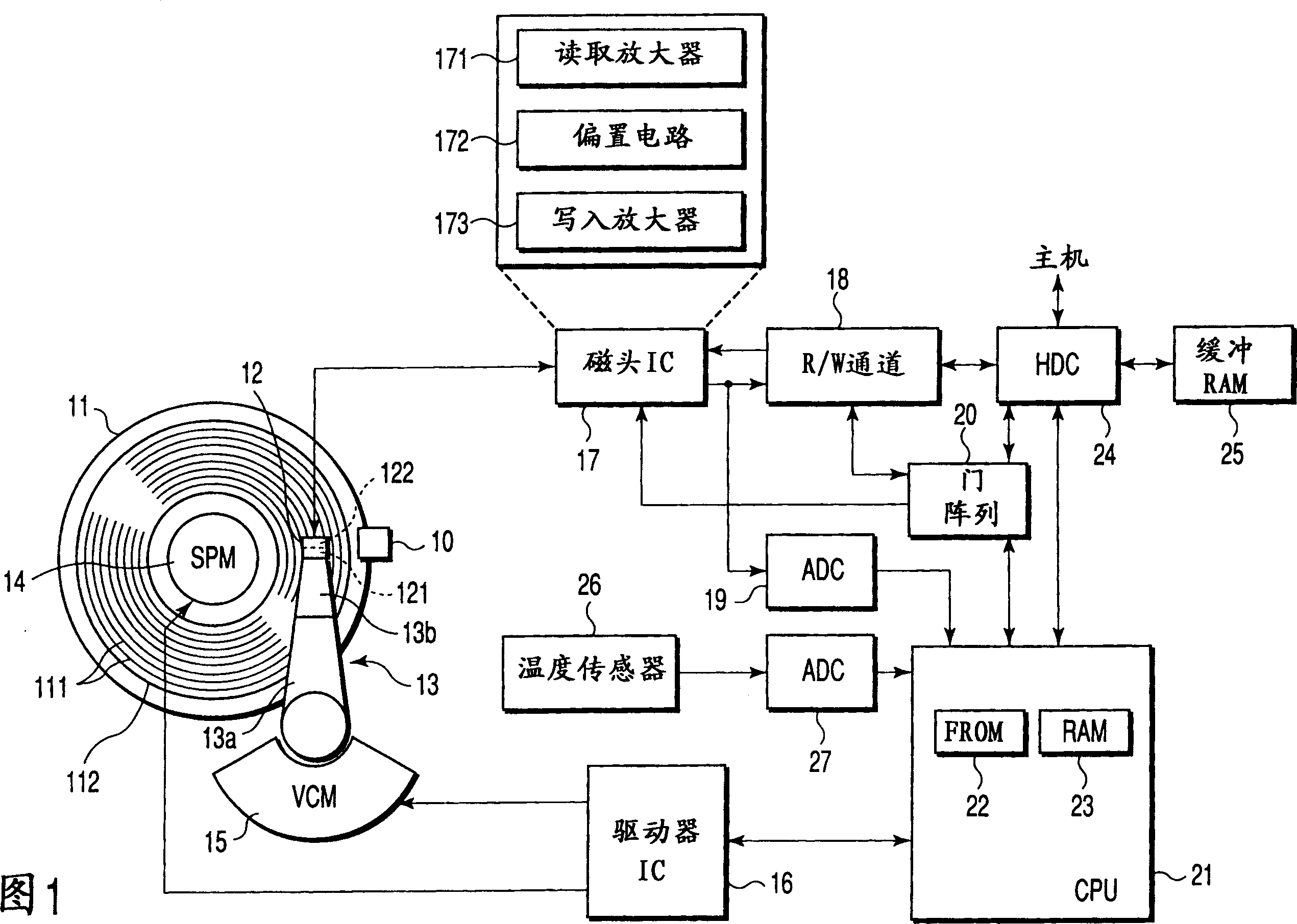
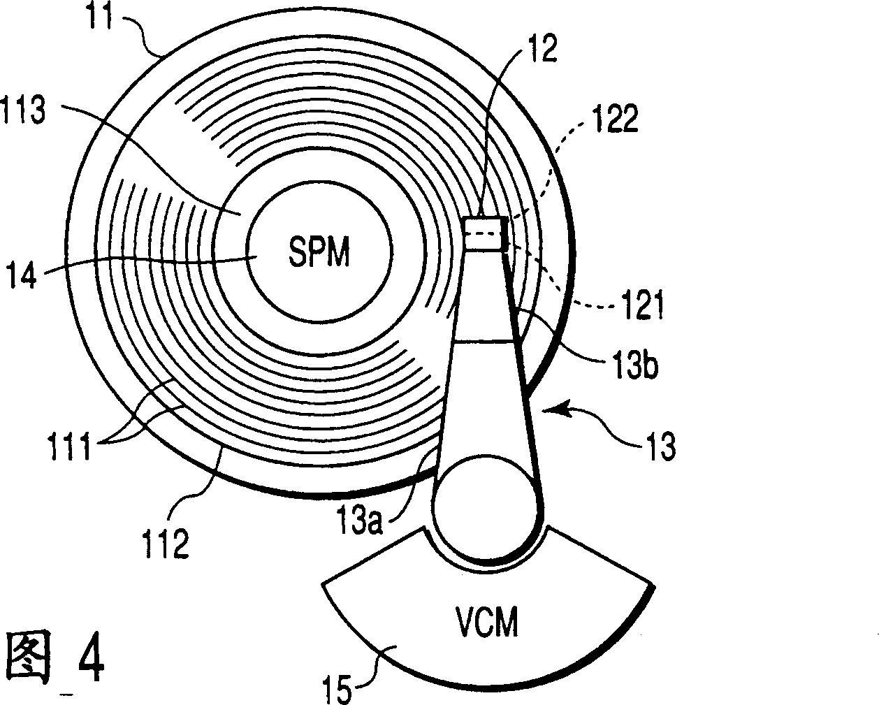
[0016] FIG. 1 is a block diagram illustrating the configuration of a hard disk drive according to a first embodiment of the present invention. In the hard disk drive (hereinafter referred to as HDD) shown in FIG. 1 , a disk medium (disk medium) 11 has two upper and lower disk surfaces. One or both disk surfaces of the magnetic disk medium 11 serve as recording surfaces on which data is magnetically recorded. A ring data area 112 is fixed on each recording surface of the magnetic disk medium 11 . The data area 112 includes a plurality of concentric tracks (data tracks) 111 . A head (magnetic head) 12 is provided for each recording surface of the magnetic disk medium 11 . The magnetic head 12 is used to write data to the magnetic disk medium 11 (data recording) and to read data from the magnetic disk medium 11 (data reproduction). The magnetic head 12 is a combined magnetic head including a read head 121 and a write head 122 integrated on a single slider. The read head 121 i...

no. 2 example

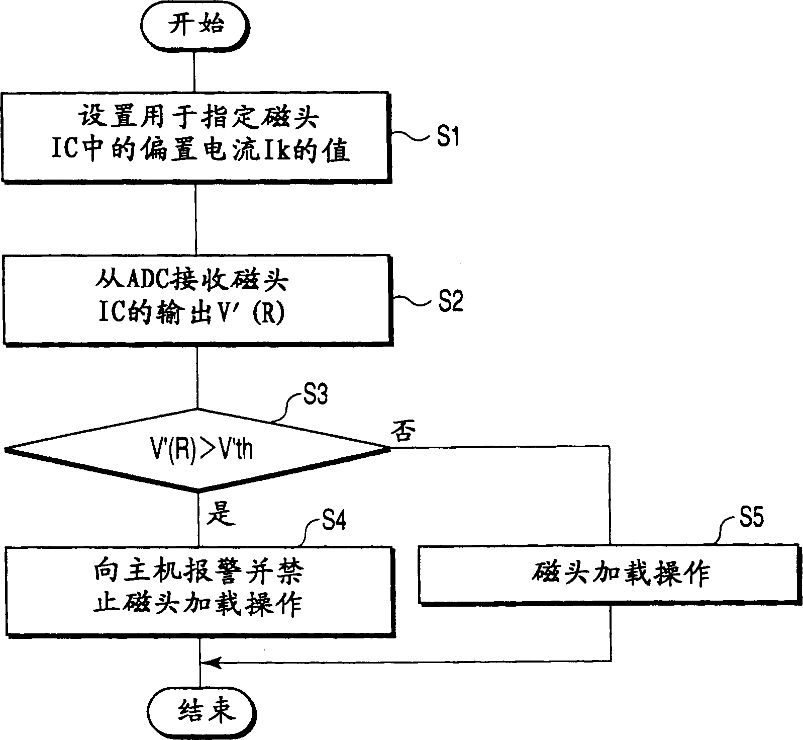
[0042]FIG. 3 is a block diagram of a configuration of a hard disk drive (HDD) according to a second embodiment of the present invention. In FIG. 3, the same parts as those in FIG. 1 are denoted by the same reference numerals. The HDD shown in FIG. 3 is characterized in that the read head 121 is not used as a magnetic field sensor for detecting a magnetic field applied to the HDD, but a special-purpose magnetic field sensor 30 for this purpose is provided. The magnetic field sensor 30 detects a magnetic field applied to the HDD and converts the magnetic field into, for example, a voltage. ADC19 converts the detection output of the magnetic field sensor 30 into a digital value. The CPU 21 receives digital values ​​from the ADC 19 when it performs head loading. Then, like in step S3 of the first embodiment, the CPU 21 compares the digital value with a predetermined threshold. If the CPU 21 loads the magnetic head 12 on the data area 112 of the magnetic disk medium 11, it deter...


PUM


Abstract

A head IC amplifies an output of a read head including MR elements and an ADC converts the amplified output into a digital value. When a CPU performs a head load operation to load a composite head including the read head onto a data area of a disk medium from a ramp, the CPU receives the output of the read head amplified by the head IC as a detection result of an external magnetic field applied to an HDD. The CPU determines whether the head load operation is performed or inhibited based on the received, amplified output of the read head, that is, the detection result of the external magnetic field applied to the HDD.

Description

technical field [0001] The present invention relates to a magnetic disk drive device with a head retracting mechanism, and more particularly, to an apparatus and method for detecting a magnetic field externally applied to the device and controlling execution of a head loading operation based on the detection result. Background technique [0002] A hard disk drive is considered as a disk drive that uses disk media as a storage medium. In a hard disk drive, a head (magnetic head) is used to read data from or write data to the magnetic disk media. If the operation of reading / writing data is performed in an environment where a magnetic field is applied externally to the hard disk drive, data on the disk media may be destroyed under the influence of the externally applied magnetic field. Recently, electronic devices such as personal computers incorporating hard disk drives have become thinner and smaller, and thus hard disk drives are susceptible to external magnetic fields. ...

Claims


Application Information

Patent Timeline
Patent Type & Authority Applications(China)
IPC IPC(8): G11B5/39G11B5/00G11B5/012G11B5/54G11B21/12
CPCG11B5/012G11B5/54G11B2005/001G11B21/12
Inventor 川名直昭海田克彦
Owner KK TOSHIBA
Why Eureka
Try Eureka