Disk drive device

A disk drive and disk technology, applied in the direction of recording information storage, instruments, etc., can solve the problems of weakening the strength of the tray 203 and not protecting the bottom

Inactive Publication Date: 2004-02-18
CITIZEN WATCH CO LTD
View PDF2 Cites 0 Cited by
  • Summary
  • Abstract
  • Description
  • Claims
  • Application Information

AI Technical Summary

Problems solved by technology

[0016] However, the part located outside the right side guide rail 206 of the magnetic disk placed on the tray 203 (that is, the part superimposed on the high platform 216) is exposed without being protected.
In addition, since the width of the disk protection part 211 is not as wide as the diameter of the disk, the strength of the tray 203 is weakened.

Method used


Image

  • Disk drive device
  • Disk drive device
  • Disk drive device

Examples


Embodiment Construction

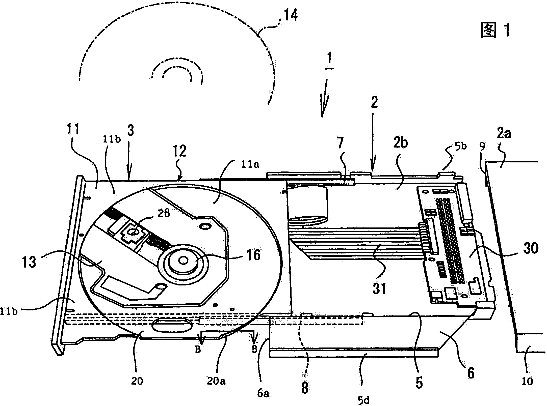
[0031] As shown in FIG. 1 , the disk drive device 1 includes a main body chassis 2 and a tray 3 . The main body chassis 2 is a stamped and formed steel plate, and consists of a top plate 2a and a bottom plate 2b.

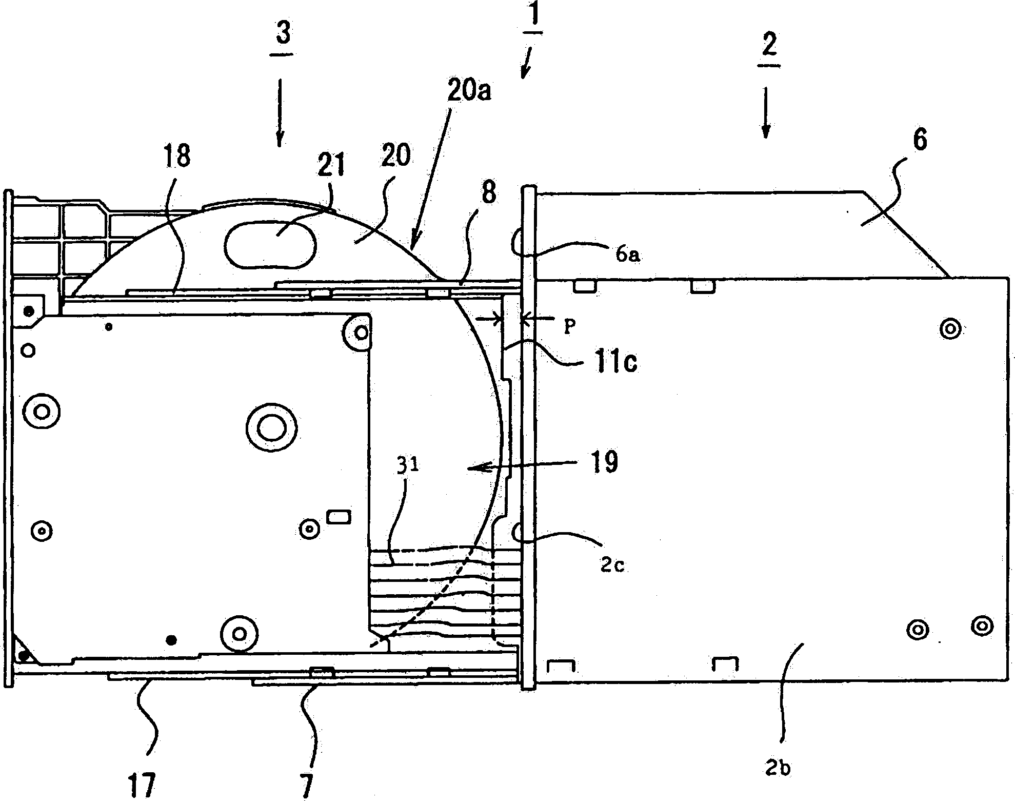
[0032] The top plate 2a is formed with side walls 9 and 10 on its left and right sides. Bottom plate 2b as figure 2 As shown in the sectional view of , side walls 4 and 5 are formed on the left and right sides thereof. The right side wall 5 is composed of a first right side wall 5c rising from the bottom end of the bottom plate 5a and a high platform portion 6 extending horizontally (to the right) from the upper end of the first right side wall 5c to the outside. The second right side wall 5d standing from the front end edge of the portion 6 is formed.

[0033] When making the top plate 2a cover the bottom plate 2b, as figure 2 As shown, the left side wall 9 of the top panel 2a is connected to the left side wall 4 of the bottom panel 2b, and the right side wal...


PUM


Abstract

A disk drive device (1), comprising a body chassis (2) and a tray (3) movable relative to the body chassis (2), the body chassis (2) further comprising a platform part (6) higher than a center bottom surface provided on one side thereof, wherein the portion of the disk protective part (11) of the tray (3) overlapped on the platform part (6) is cut out in arc shape at the rear end (20a) thereof, whereby the disk protective part (11) covers all areas of a disk (14) and forms a large space from the front end (6a) of the platform part (6).

Description

technical field [0001] The present invention relates to a disk drive device for mounting and driving information recording disks such as compact disks (CDs) and digital video disks (DVDs), and reading information from or inputting information to the disks. Background technique [0002] A disk drive unit is incorporated into a parent unit such as a microcomputer. refer to Figure 8 A first example of a conventional magnetic disk drive device will be described. This example is an example disclosed in JP-A-8-138296. [0003] The disk drive device is composed of a main body chassis 102 installed in the microcomputer and a tray 103 on which the disk is installed. A left slide bar 140 is installed on the left side wall of the tray 103 , and a right slide bar 141 is installed near the right end below the tray 103 . [0004] On the one hand, a left sliding guide rail 150 is formed on the left side wall of the main body chassis 102 , and a right sliding guide rail 151 is formed on...

Claims


Application Information

Patent Timeline
Patent Type & Authority Applications(China)
IPC IPC(8): G11B17/04
CPCG11B17/056
Inventor 高桥昇司胁口真纪神山卓郎
Owner CITIZEN WATCH CO LTD
Why Eureka
Try Eureka