

Dry-ice blast device
A spraying device and dry ice technology, applied in the direction of abrasive feeding device, abrasive, metal processing equipment, etc., can solve the problems of waste, large amount of wear, high price, etc.
- Summary
- Abstract
- Description
- Claims
- Application Information
AI Technical Summary
Problems solved by technology
Method used
Image

Examples
Embodiment Construction
[0032] Hereinafter, preferred embodiments of the present invention will be specifically described with reference to the drawings.
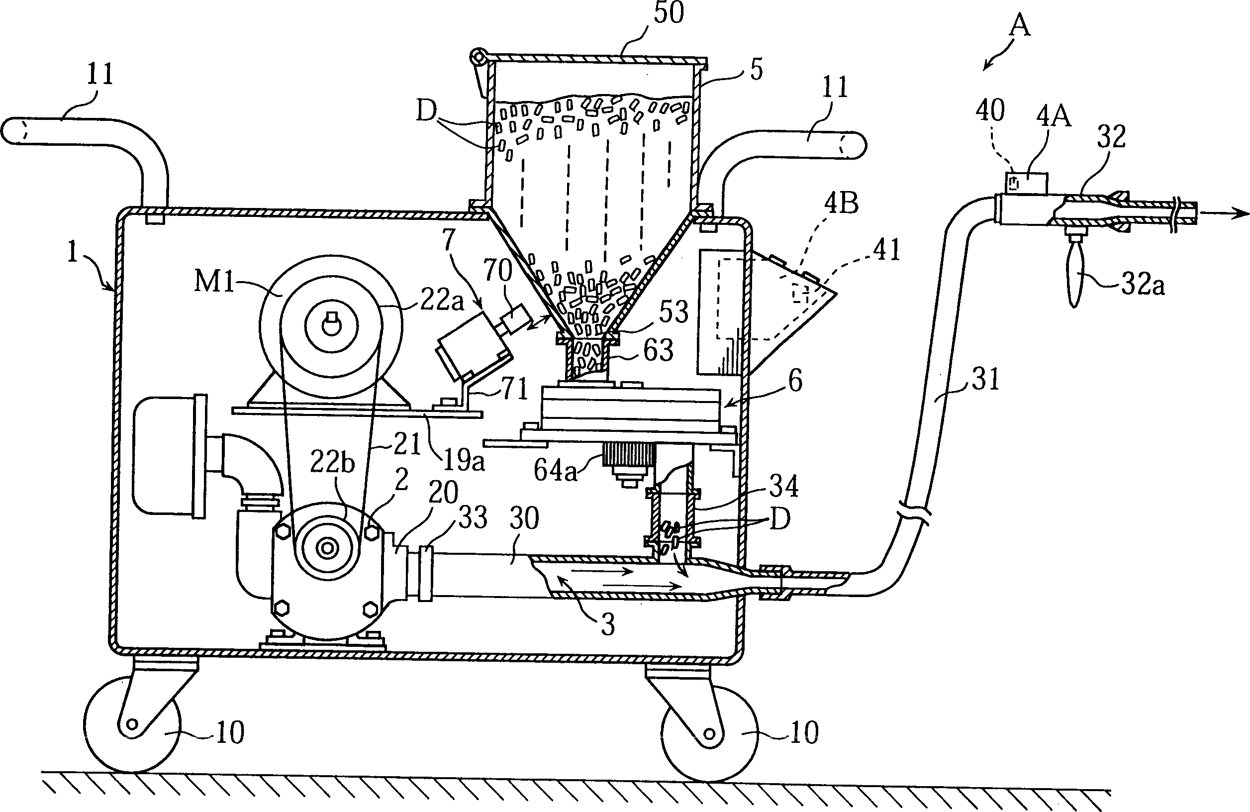
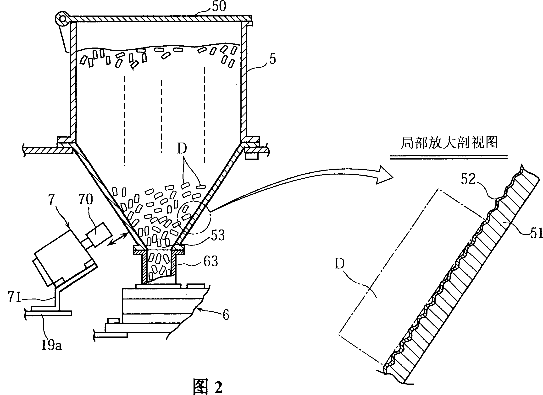
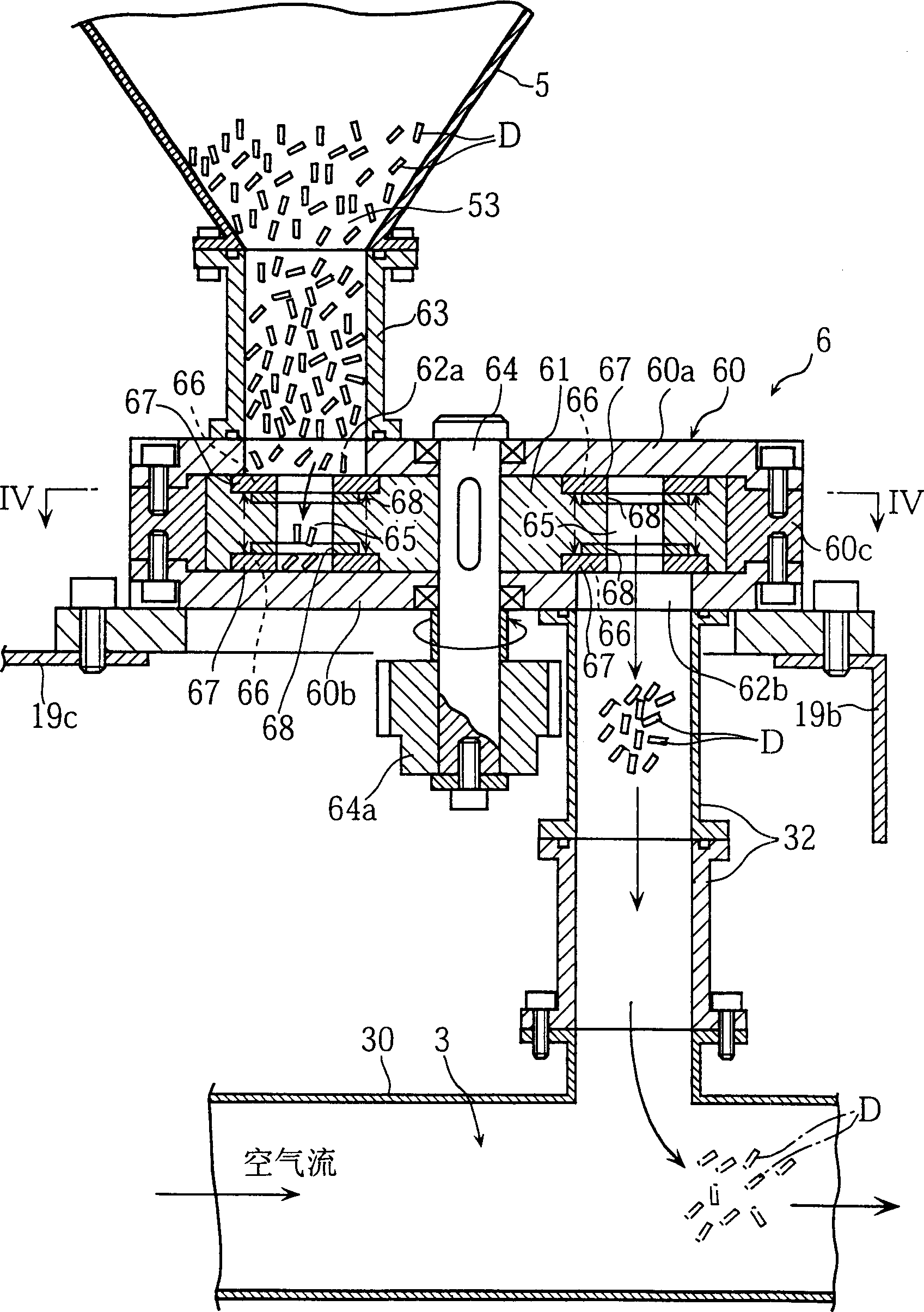
[0033] figure 1 An embodiment of the dry ice blasting apparatus of the present invention is shown. The dry ice blasting device A of this embodiment has a movable frame 1, an air compressor 2, a pipe body 30 connected to the output pipeline 20 of the air compressor 2, a hose 31, a nozzle 32, an operation part 4A, and a control part 4B. , hopper 5, rotary feeder 6 and door hammer 7.
[0034] The movable frame 1 is formed in an approximate box shape as a whole, and constitutes other components of the dry ice blasting device A, which are directly or indirectly installed on the movable frame 1 . The movable frame 1 has a plurality of wheels 10 and is easy to move on the ground. On the upper part of the movable frame 1, one or more handles 11 are installed.
[0035] The air compressor 2 is (for example) a Roots blower (Lu tsu ズロア), and the outlet pr...
PUM
| Property | Measurement | Unit |
|---|---|---|
| diameter | aaaaa | aaaaa |
| length | aaaaa | aaaaa |
Abstract
Description
Claims
Application Information