Method and arrangement for defrosting vapor compression system

A compressor and vapor compression technology, applied in the direction of compressors, irreversible cycle compressors, and reversible cycle compressors, etc., can solve the problem of low refrigerant temperature, long defrosting time, and limited transfer to heat accumulators. temperature difference

Inactive Publication Date: 2003-12-10
SINVENT AS
View PDF2 Cites 7 Cited by
  • Summary
  • Abstract
  • Description
  • Claims
  • Application Information

AI Technical Summary

Problems solved by technology

Another disadvantage of this system is that the temperature of the refrigerant in the accumulator must be above 0°C, which limits the effective temperature difference for heat exchange to the accumulator
[0004] Finally, another disadvantage of this system is the relatively low temperature of the refrigerant in the heat exchanger to be defrosted, resulting in a long defrosting time

Method used


Image

  • Method and arrangement for defrosting vapor compression system
  • Method and arrangement for defrosting vapor compression system
  • Method and arrangement for defrosting vapor compression system

Examples


Embodiment Construction

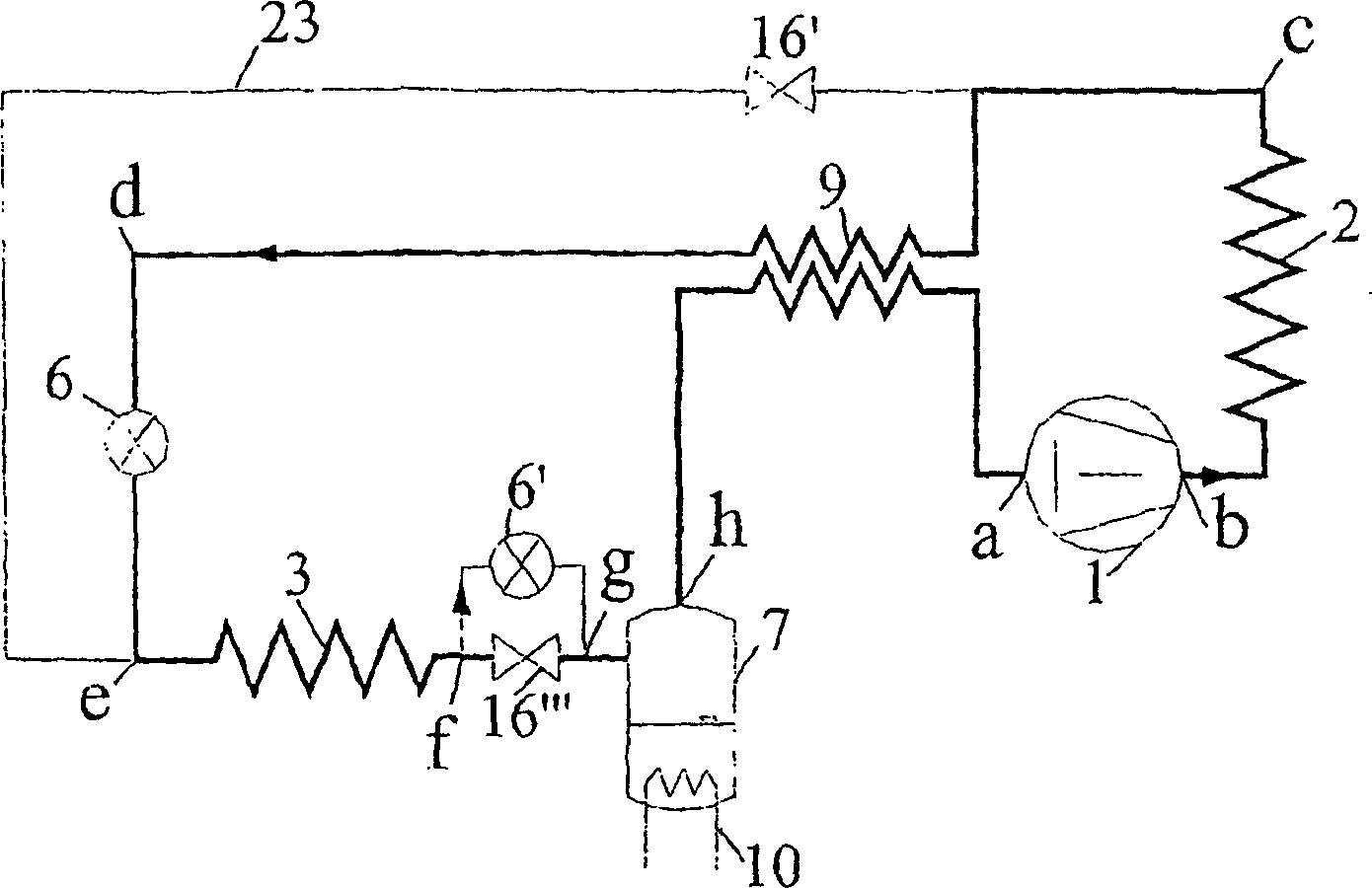
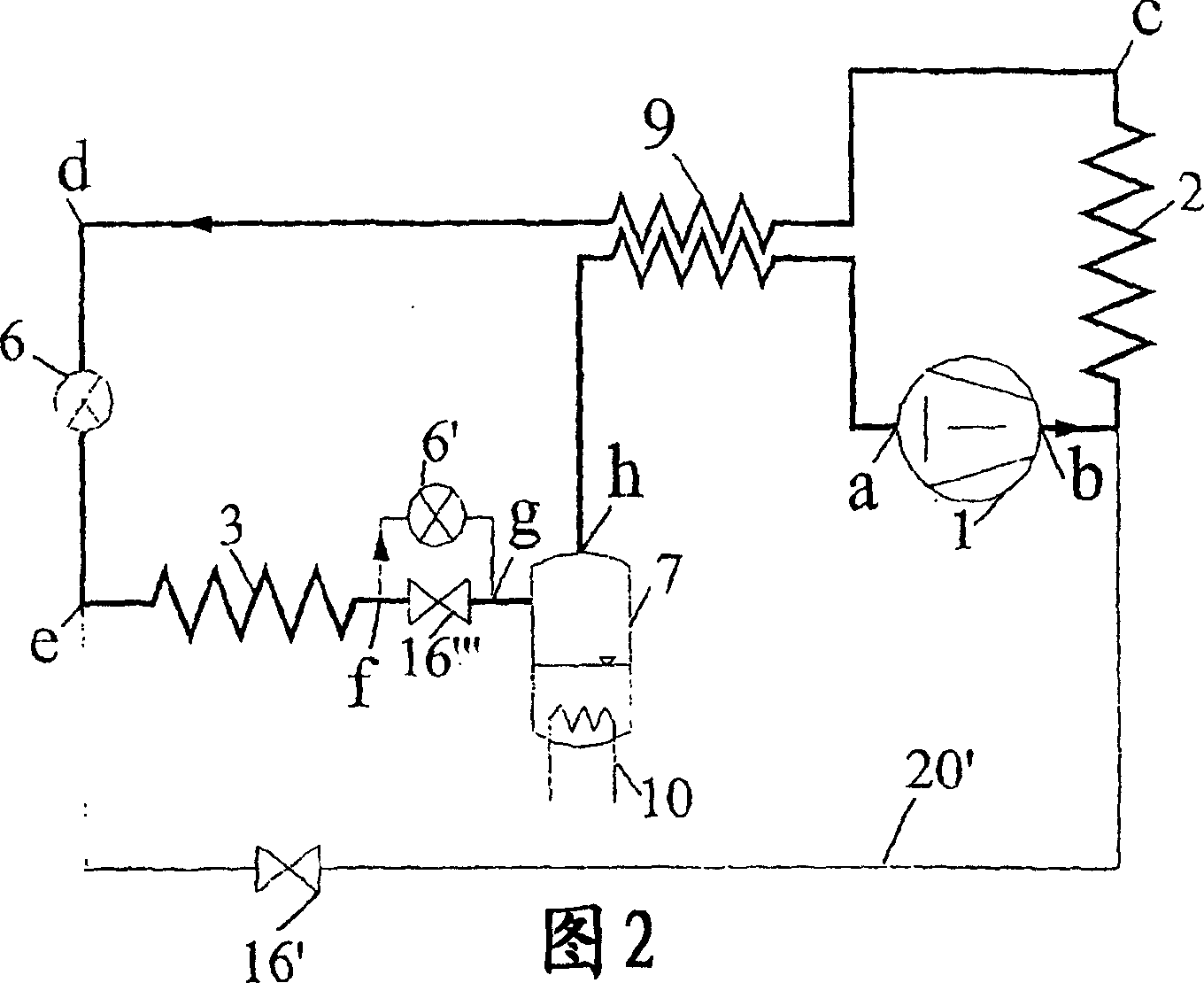
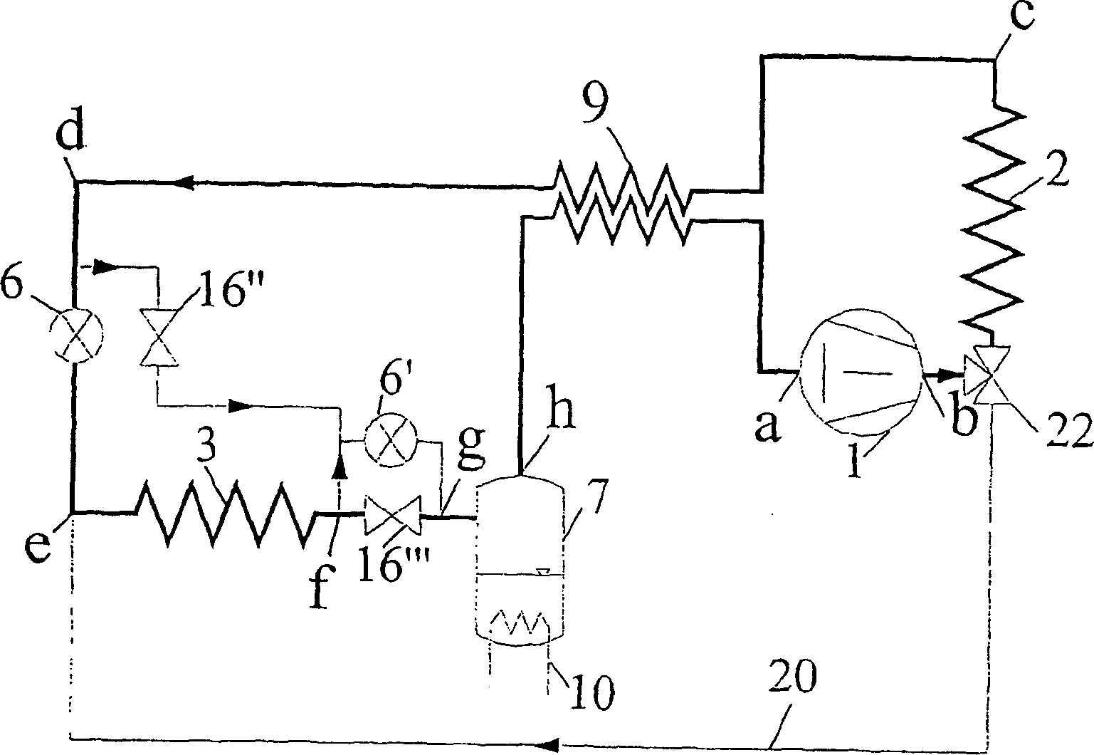
[0016] The present invention relates to refrigeration and heat pump systems, and more particularly to the defrosting of frosted heat exchangers, especially evaporators, in supercritical processes, where the refrigerant can be any fluid, especially carbon dioxide, but the present invention is not limited thereto.

[0017] The invention can be used in any refrigeration and heat pump system which preferably has a pressure receiver / reservoir. If desired, the present invention also vents the internal cooling airflow during the defrost cycle, which is the same as conventional defrost methods in heat pump systems. This can be achieved by an external heat source such as an electrical resistance or waste heat (eg from a car radiator cooling system) or any other suitable device that can be incorporated into the receiver / reservoir, or a connecting pipe along the refrigerant path in the circuit. Heat can also be provided from storage. The invention can be used in both subcritical and su...


PUM


Abstract

Method for defrosting of a heat exchanger (evaporator) in a vapor compression system including, beyond a heat exchanger (evaporator) (3) to be defrosted, at least a compressor (1), a second heat exchanger (condenser / heat rejecter) (2) and an expansion device (6) connected by conduits in an operable manner to form an integral closed circuit. The heat exchanger (3) to be defrosted is subjected to essentially the same pressure as the compressor's (1) discharge pressure whereby the heat exchanger (3) is defrosted as the high-pressure discharge gas from the compressor (1) flows through to the heat exchanger, giving off heat to the said heat exchanger (3).

Description

technical field [0001] The invention relates to a defrosting method and device for a heat exchanger (evaporator) in a refrigeration or heat pump system. In addition to the first heat exchanger (evaporator), the system also includes at least one compressor, a second heat exchanger ( thermal suppressor) and an expansion device are operatively connected by piping to form an integral closed circuit. Background technique [0002] In some applications, such as air source heat pumps or air coolers in refrigeration systems, when the ambient temperature is close to or below the freezing point of water, frost can form on the heat-absorbing heat exchanger (used as an evaporator). Due to the accumulation of frost, the heat transfer performance of the heat exchanger is reduced, and thus the system performance is reduced. Therefore a defrosting device is required. The most conventional defrosting methods are electric defrosting and hot gas defrosting. When the system has two or more ev...

Claims


Application Information

Patent Timeline
Patent Type & Authority Applications(China)
IPC IPC(8): F25B1/00F25B1/10F25B9/00F25B13/00F25B40/00F25B43/00F25B47/02
CPCF25B40/00F25B13/00F25B9/008F25B2313/023F24F3/1405F25B2600/2501F25B2309/061F25B2400/16F25B47/022F25B1/10F24F2003/1446F25B47/02
Inventor 卡利·阿弗莱科特埃纳尔·布伦登阿明·哈弗奈尔皮特·尼卡萨约斯坦恩·皮特森哈弗·雷科斯塔德吉尔·斯考根格拉姆·雷萨·扎科利
Owner SINVENT AS
Why Eureka
Try Eureka