Antifriction bearing for a steering column

An anti-wear, bearing technology, applied in the direction of rotating bearings, steering columns, bearings, etc., can solve problems such as high risk

Inactive Publication Date: 2004-12-01
AB SKF
View PDF1 Cites 6 Cited by
  • Summary
  • Abstract
  • Description
  • Claims
  • Application Information

AI Technical Summary

Problems solved by technology

[0007] Also, in order to mount the gasket on the elastic element, said gasket is axially compressed at the risk of turning itself over, this risk being even greater if the gasket is thin as described above

Method used


Image

  • Antifriction bearing for a steering column
  • Antifriction bearing for a steering column
  • Antifriction bearing for a steering column

Examples


Embodiment Construction

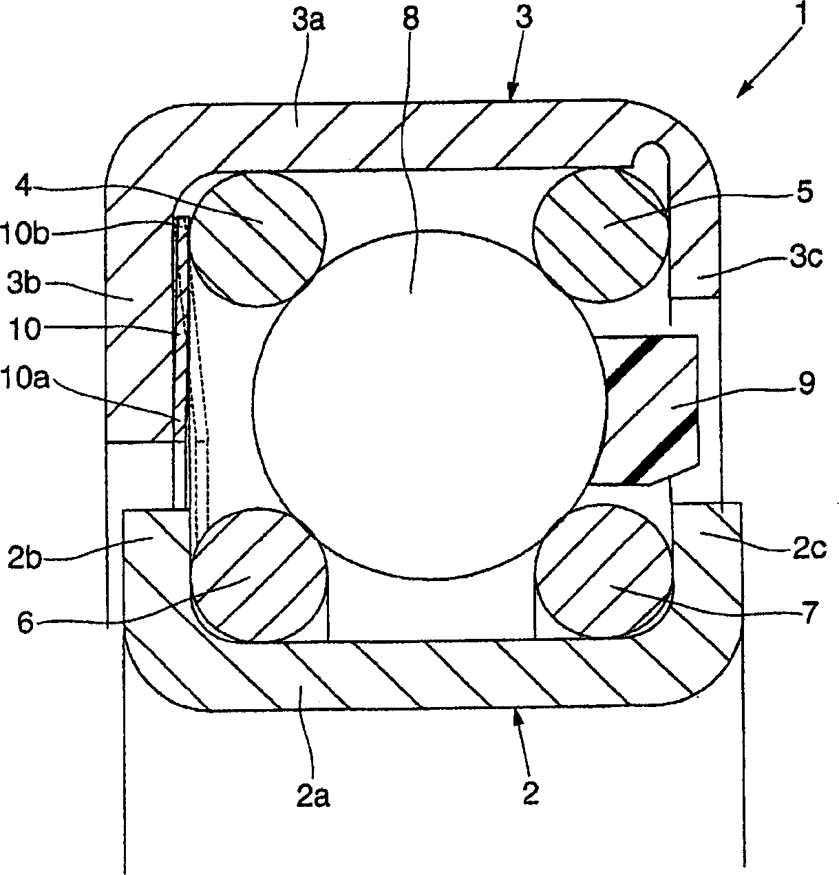
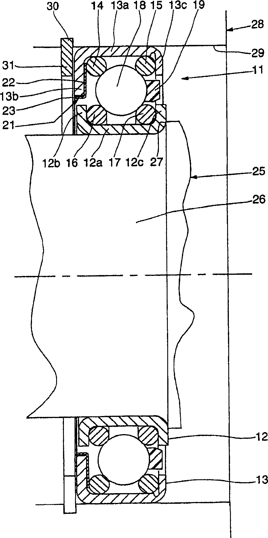
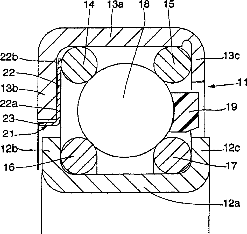
[0032] Such as figure 1 As shown, a bearing 1 includes an inner sheath 2 , an outer sheath 3 , four wires 4 , 5 , 6 and 7 , a row of rolling elements 8 , a cage 9 and a Belleville washer 10 . The inner ring 2 comprises an axial portion 2a extending at each of its axial ends with radial portions 2b, 2c. The radial sections 2b and 2c are identical. The inner sheath 2 thus exhibits a ring shape with a U-shaped cross-section.

[0033] The outer sheath 3 also has a ring of U-shaped cross-section and an axial portion 3a, a radial wall 3b and a radial wall 3c. The thickness of the radial wall 3c is smaller than the thickness of the axial portion 3a and the thickness of the radial portion 3b, and the length in the radial direction is smaller than the length of the radial portion 3b. In other words, the interval separating the radial portions 2c and 3c is greater than the interval separating the radial portions 2b and 3b.

[0034] Wires 4 and 5 are arranged in an outer sheath, whil...


PUM


Abstract

The invention relates to an antifriction bearing for a steering column. The inventive device comprises an outer ring and an inner ring, each of said rings being fitted with a raceway for rolling elements (8) which are in contact with said raceways. At least one of the rings comprises an annular casing (3) to which two wires (4, 5) are mounted which form a raceway for the rolling elements (8). Moreover, said device comprises a preload washer (10) which is mounted axially between a radial portion of the casing (3) and one of the wires. The aforementioned wire is in contact with the bore of an axial portion of the casing (3) and another wire is also in contact with the bore of said axial portion of the casing (3).

Description

technical field [0001] The invention relates to the field of anti-wear bearings, in particular for steering columns. Background technique [0002] Document FR-A-2 669 690 discloses a bearing comprising an outer ring of U-section, an inner ring of U-section, an elastic element placed in the outer ring and four treated steel wires, two of which The steel wire is placed in the inner ring, in the connecting area between its axial part and the radial part, while the other two are in the holes of the elastic element, and the rolling elements placed in contact with the steel wires that make up the raceways of the rolling elements Components such as ball bearings. The wire is in the shape of a retaining ring with the ends connected end to end when it is in place. The rolling elements can be adjacent to each other in the circumferential direction or evenly spaced from each other by means of a cage. The elastic element exhibits an annular L-section form, the axial part of which is ...

Claims


Application Information

Patent Timeline
Patent Type & Authority Applications(China)
IPC IPC(8): B62D1/16F16C19/06F16C19/16F16C23/08F16C25/08F16C33/61
CPCF16C33/61F16C19/166F16C2326/24F16C25/08
Inventor 雅克・德洛斯布鲁诺・蒙特博尤夫西尔万・巴西特
Owner AB SKF
Why Eureka
Try Eureka