Reactive optimizing method of power system based on coordinate evolution

A co-evolution and power system technology, applied in reactive power compensation, control/regulation system, reactive power adjustment/elimination/compensation, etc., can solve problems such as increasing the difficulty of reactive power optimization problems

Inactive Publication Date: 2005-01-12
XI AN JIAOTONG UNIV
View PDF0 Cites 26 Cited by
  • Summary
  • Abstract
  • Description
  • Claims
  • Application Information

AI Technical Summary

Problems solved by technology

[0022] 2 Existing methods for reactive power optimization problems
These problems increase the difficulty of solving the reactive power optimization problem

Method used


Image

  • Reactive optimizing method of power system based on coordinate evolution
  • Reactive optimizing method of power system based on coordinate evolution
  • Reactive optimizing method of power system based on coordinate evolution

Examples


Embodiment Construction

[0105] The present invention will be described in further detail below in conjunction with the accompanying drawings.

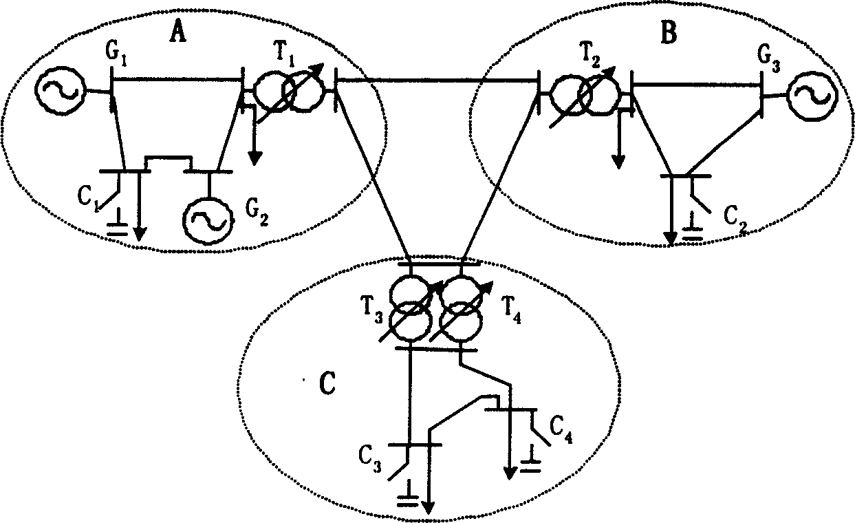
[0106] see figure 1 , in order to illustrate the principle of the present invention, a simple system is used here as an example, the system is composed of three power supply areas A, B, C, each power supply area is a sub-problem of reactive power optimization, in optimization, use A population to represent, . where C 1 , T 1 , G 1 Respectively, the compensation capacitance (reactance), on-load voltage regulating transformer, and adjustable voltage generator in area A; C 2 , T 2 , G 3 They are the compensation capacitance (reactance), on-load voltage regulating transformer, and adjustable voltage generator in area B; C 3 、C 4 Respectively two compensation capacitors (reactances) in area C, T 3 , T 4 They are two on-load voltage regulating transformers in area C respectively. The actual power system with reactive power optimization may be more figur...


PUM


Abstract

The method includes following steps: dividing control variables (as plant or animal communities) for system reactive optimization into several groups, and each variable is corresponding to a flock in coevolution method; inputting original data, initializing each flock, calculating adaptation function value of each chromosome in initial flocks; based on previous generation, generating new generation through genetics operations of selection, chiasma, variation; calculating adaptation function value fro new generation; selecting optimum chromosome; evolutionary optimization of ecosystem is completed after optimizing each flock; determining whether condition of convergence of genetic algorithm is met, and outputting optimized result. In the invention, problem to be solved is mapped to ecosystem including multiple flocks. Coevolution of interactive flocks makes optimization of system.

Description

technical field [0001] The present invention relates to a method for reactive power optimization of electric power system, in particular to a method for reactive power optimization of electric power system based on co-evolution Background technique [0002] Reactive power management is required in power systems to control voltage levels and reduce active losses. Commonly used reactive power / voltage control methods include generator voltage, transformer tap position, shunt capacitor and reactor bank, etc. The reactive power management in the power system can be divided into: reactive power planning, reactive power operation planning, reactive power scheduling and control, etc. Reactive power planning is to determine the installation location and quantity of reactive power equipment in the system. It is necessary to reduce the investment of reactive power equipment and optimize the reactive power operation of the system; reactive power operation planning is to use existing re...

Claims


Application Information

Patent Timeline
Patent Type & Authority Applications(China)
IPC IPC(8): G05F1/70H02J3/18
CPCY02E40/30
Inventor 陈皓勇王锡凡王建学胡泽春
Owner XI AN JIAOTONG UNIV
Why Eureka
Try Eureka