
Multiple output converter with improved cross regulation

A converter and mutual voltage stabilization technology, applied in the field of multiple output rectifiers, can solve problems such as low conduction voltage drop

Inactive Publication Date: 2005-02-02
DELTA ELECTRONICS INC
View PDF0 Cites 11 Cited by
  • Summary
  • Abstract
  • Description
  • Claims
  • Application Information

AI Technical Summary

Problems solved by technology

Due to the lower conduction voltage drop (conductionVoltage drop) of the synchronous rectifier compared with the diode rectifier, and due to the continuous current mode (continus conduction mode, CCM) operation of the first output circuit 501, the two output circuits 501 , 502 in the worst operating environment where the output circuit 502 is light-loaded, it will cause several voltage regulation problems

Method used


Image

  • Multiple output converter with improved cross regulation
  • Multiple output converter with improved cross regulation
  • Multiple output converter with improved cross regulation

Examples


Embodiment Construction

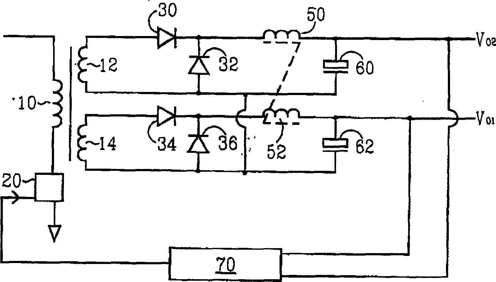
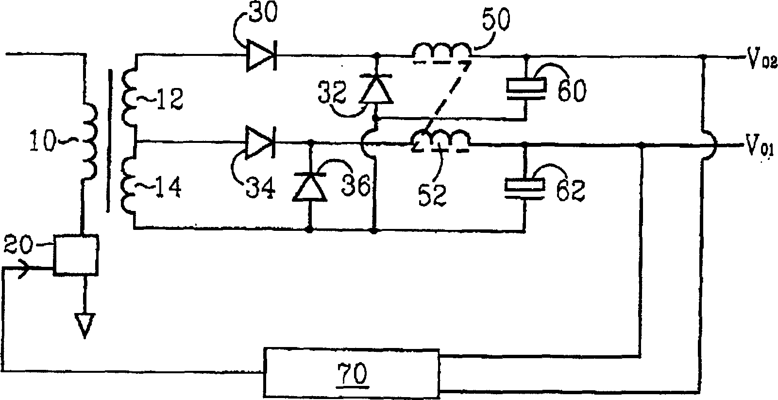
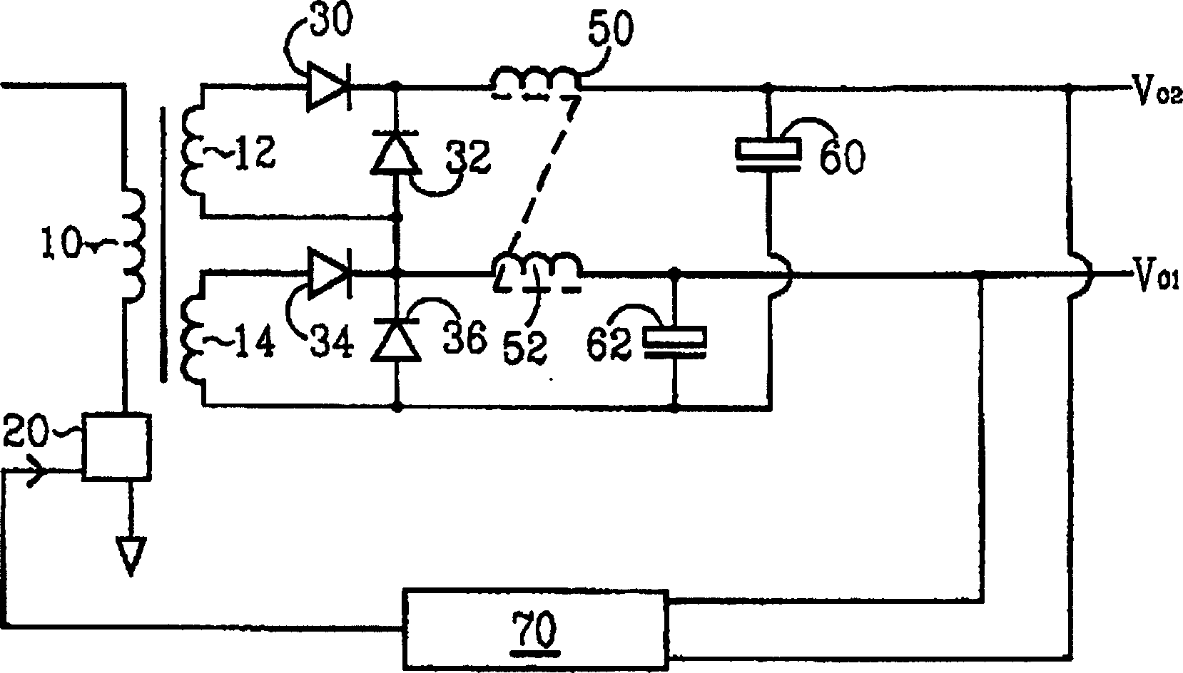
[0027] Please refer to Figure 5 , Figure 5 It is a schematic diagram of a dual-output DC / DC converter with improved mutual stability according to the first embodiment of the present invention. The converter includes a transformer having a primary winding 110 coupled to an input transistor switching circuit 120 , a first secondary winding 114 and a second secondary winding 112 . The input transistor switching circuit 120 includes at least one transistor switch (not shown). The converter further includes a first output circuit and a second output circuit; the first output circuit includes a synchronous rectifier connected to the first secondary coil 114 to provide a first output voltage Vo1, the second output circuit includes A diode rectifier connected to the second secondary coil 112 to provide a second output voltage Vo2. The synchronous rectifier of the first output circuit includes a forward MOSFET 140 and a freewheeling MOSFET 144 . The diode rectifier of the second ...


PUM


Abstract

A cost effective circuit improves the cross regulation of multiple outputs converter, especially for that output chokes are coupled and a synchronous rectifier is applied to one of the outputs. A DC / DC converter includes a transformer having a primary winding and two secondary windings. The first secondary winding is coupled to a synchronous rectifier and a first output choke. The second secondary winding is coupled to a diode rectifier and a second output choke. The first output choke and the second output choke are coupled. A low power MOSFET switch is added to the diode rectifier for avoiding the diode rectifier operating in DCM when light loaded.

Description

technical field [0001] The present invention relates to an output rectifying circuit of a switching power supply, in particular to a multiple output rectifier using a synchronous rectifier and a diode rectifier at the same time. Background technique [0002] A DC / DC converter is mainly used to provide power to electronic devices such as computers, communication devices, and personal digital assistants. DC / DC converters are used to convert a DC input voltage into one or more regulated DC output voltages. For example, for personal computer or networking applications, a DC / DC converter can be used to convert an input voltage into three main DC outputs (12V, 5Y, 3.3V). [0003] figure 1 A prior art multiple output forward converter (ForwsrdConvertef) is described. The forward converter includes a primary coil 10 input transistor switching circuit 20 coupled to a transformer. In the specific example described here, the input transistor switching circuit is typically a power s...

Claims


Application Information

Patent Timeline
Patent Type & Authority Applications(China)
IPC IPC(8): H02M3/145H02M3/28H02M3/335
CPCH02M3/33592H02M2001/009Y02B70/1475Y02B70/10H02M1/009
Inventor 甘鸿坚窦森章进法钟天富程伟巴圣塔那克罗
Owner DELTA ELECTRONICS INC
Learn More