
Housing for a butterfly needle

A shell and fin technology, applied in the directions of needles, guiding needles, and instruments introduced into the body, etc., can solve problems such as pain

Inactive Publication Date: 2005-03-02
SARSTEDT AG & CO KG
View PDF1 Cites 8 Cited by
  • Summary
  • Abstract
  • Description
  • Claims
  • Application Information

AI Technical Summary

Problems solved by technology

But this movement brings pain

Method used


Image

  • Housing for a butterfly needle
  • Housing for a butterfly needle
  • Housing for a butterfly needle

Examples


Embodiment Construction

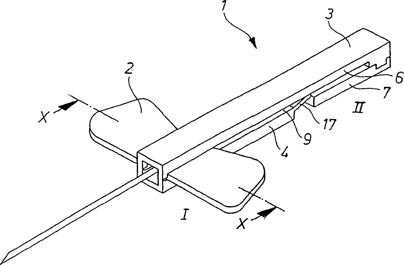
[0015] figure 1 Shown is a housing 1 accommodating a winged needle 2 in a long known lancing device including the used winged needle. The housing comprises a top cover 3 and a bottom cover 4 . In the illustrated embodiment, the top cover 3 is as wide as the bottom cover 4 . However, the top cover 3 can also be narrower than the bottom cover 4 .

[0016] The top cover 3 is connected to the bottom cover 4 , for example via a film hinge. After the wing needle 2 has been inserted, the top cover 3 and the bottom cover 4 are locked, for example by hooking.

[0017] Another possibility consists in locking the top cover 3 and the bottom cover 4 on both sides. The side walls 6 or 7 of the top cover 3 or bottom cover 4 , which adjoin each other at a vertical distance, can provide a horizontal gap 8 for the guide groove 9 of the wing pin.

[0018] If the top cover 3 is narrower than the bottom cover 4, a horizontal slot 8 and a vertical slot 10 are formed through which the wings of ...


PUM


Abstract

The invention relates to a protective housing (1) for a butterfly needle (2), which comprises an elongate lower cap (4) and an elongate upper cap (3), each having a substantially U-shaped cross-section, that can be closed to give a housing unit once the wings of the butterfly needle (2) are inserted. Guide grooves (9) are defined by free gap distance on both sides between the adjacent vertical side walls (6, 7) of the caps (3, 4). An upstream spring-loaded element (17) projects in a constant locking position (II) from at least one of the side walls (6 or 7) into one of the guide grooves (9).

Description

technical field [0001] The present invention relates to a housing for a wing needle, comprising a bottom cover extending approximately in a U-shape in cross-section and an extended top cover, said top cover and bottom cover being connected to each other, and where the fins of the wing needle are fitted to The two covers are closed at opposite ends to form the shell, provided by the covers in guide grooves on both sides provided in the longitudinal direction of the housing and forming a front retaining or locking position and a rear retaining or locking position. body unit. Background technique [0002] A needle is used for blood collection, which can be connected to the blood collection tubing via a connecting tube and an adapter, such needles have side wings. To prevent the user of such a needle from inadvertently damaging the needle, such winged needles have a shield surrounding the needle. [0003] Such an enclosure is known from EP0436646B1. In this embodiment, the ne...

Claims


Application Information

Patent Timeline
Patent Type & Authority Applications(China)
IPC IPC(8): A61M5/32A61M25/06
CPCA61M25/0631A61M5/3272A61M25/0637
Inventor W·萨斯特德特
Owner SARSTEDT AG & CO KG
Learn More