Adsorption position corrector of electronic device in electronic device mounting machine

An electronic device, adsorption position technology, applied in the direction of electrical components, electrical components, etc., can solve the problems of long installation time and low output

Inactive Publication Date: 2005-03-09
JUKI CORP
View PDF1 Cites 23 Cited by
  • Summary
  • Abstract
  • Description
  • Claims
  • Application Information

AI Technical Summary

Problems solved by technology

[0004] However, in the case of the above-mentioned Patent Document 1, since the identification of the center position of the electronic device and the correction of the suction position are performed, all the electronic devices must be photographed and corrected, so there are problems of long installation time and low yield.

Method used


Image

  • Adsorption position corrector of electronic device in electronic device mounting machine
  • Adsorption position corrector of electronic device in electronic device mounting machine
  • Adsorption position corrector of electronic device in electronic device mounting machine

Examples


Embodiment Construction

[0022] Below, refer to Figure 1 to Figure 5 Embodiments of the present invention will be described.

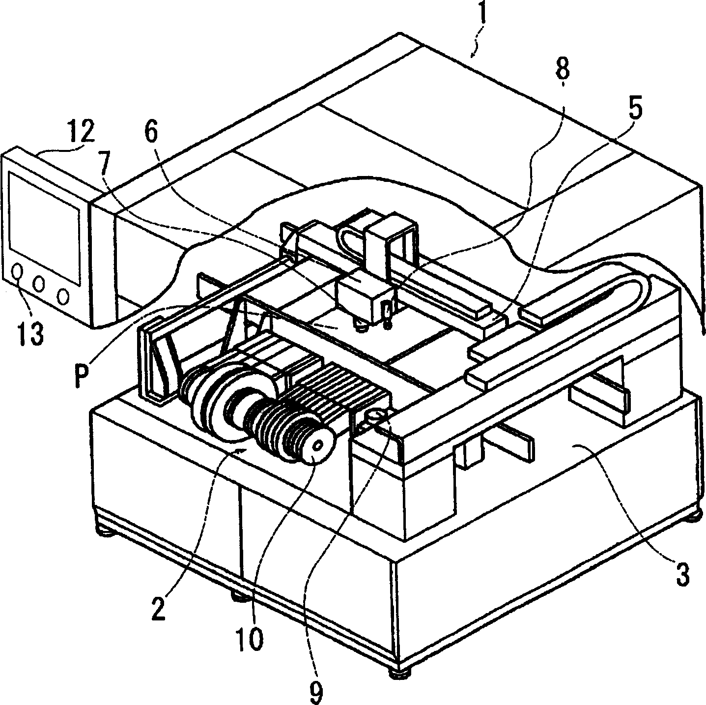
[0023] figure 1 It is a schematic diagram of an electronic component mounting machine having a suction position correcting device according to the present invention. The electronic component mounting machine 1 has a substrate conveyance path 3 extending in the left and right directions at the center, and a component supply path 3 arranged at the front of the electronic component mounting machine 1. 2 and the XY transport unit 5 provided across the substrate transport path 3 in the electronic component mounting machine 1 .

[0024] A suction head 6 for suctioning and mounting the electronic component C on the substrate P is mounted on the XY conveyance unit 5, and a plurality of suction heads 6 that can move up and down and rotate in the axial direction are provided on the suction head 6. Mouth7.

[0025] Further, a recognition camera 8 for recognizing a substrate mark (not...


PUM


Abstract

To provide an apparatus for correcting an electronic component suction position in an electronic component mounting machine for sucking an electronic component at a suitable position that is sequentially fed out by a tape feeder or the like. The apparatus includes a tape feeder for pitch-feeding an electronic component housed in a component housing hole of a tape, a camera provided on a mount head for identifying the component housing hole of the tape, a CPU for calculating the displacement between the prerecorded central standard position and the central position calculated by the identified image of the camera of the component housing hole of the tape, and a display for displaying the central reference position and the image of the component housing hole. The correction of the electronic component suction position is made possible, based on the central reference position in the display and the displayed result of the central position of the component housing hole.

Description

technical field [0001] The present invention relates to a suction position correcting device for electronic components in an electronic component mounting machine for suctioning electronic components sequentially fed out by a tape feeder or the like to appropriate positions. Background technique [0002] As a prior art electronic component mounting apparatus, there is disclosed a method in which an electronic component supplied by a tape feeder serving as a component supply unit is attracted to a suction nozzle provided on a mounting head and moved to a substrate for mounting. In the electronic component mounting machine, the electronic component mounting device recognizes the electronic component in the carrier tape storage hole in the tape feeder, and absorbs it at the center of gravity of the electronic component. [0003] [Patent Document 1] JP-A-1-155698 [0004] However, in the case of the above-mentioned Patent Document 1, since the identification of the center posit...

Claims


Application Information

Patent Timeline
Patent Type & Authority Applications(China)
IPC IPC(8): H05K13/04
Inventor 小仓丰大桥隆弘
Owner JUKI CORP
Why Eureka
Try Eureka