Liquid crystal display module

A liquid crystal display, display panel technology, used in static indicators, instruments, nonlinear optics, etc., can solve problems such as poor heat dissipation

Active Publication Date: 2005-04-06
AU OPTRONICS CORP
View PDF0 Cites 15 Cited by
  • Summary
  • Abstract
  • Description
  • Claims
  • Application Information

AI Technical Summary

Problems solved by technology

[0005] Therefore, the object of the present invention is to provide a liquid crystal display module with a high heat dissipation effect to effectively solve the problems caused by poor heat dissipation of existing liquid crystal display modules

Method used


Image

  • Liquid crystal display module
  • Liquid crystal display module
  • Liquid crystal display module

Examples


Embodiment Construction

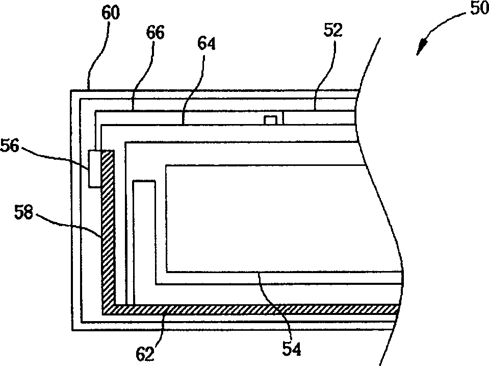
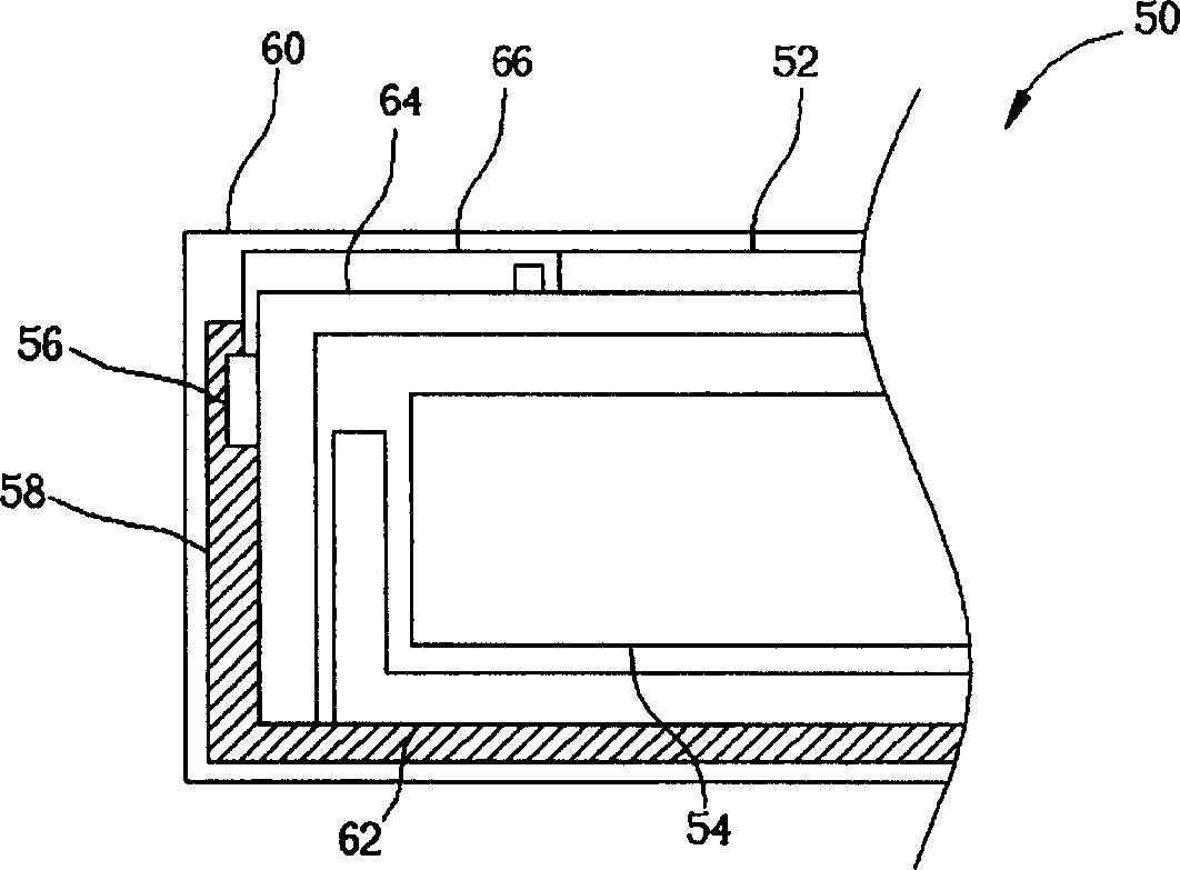
[0019] Please refer to figure 2 , figure 2 It is a schematic structural diagram of the first embodiment of the liquid crystal display module of the present invention. Such as figure 2 As shown, the liquid crystal display module 50 of the present invention includes a display panel 52, a backlight module 54 is used to provide light source, a control chip 56 is used to control the display panel 52 to display images, and a heat dissipation pad 58 is used to conduct heat generated by the control chip 56. , and a casing 60. Wherein, the backlight module 54 further includes a metal frame 62 for supporting the backlight module 54 and a casing 64 . The control chip is disposed on the side of the backlight module 54 using a carrier tape (TAB tape) 66 (or a flexible printed circuit board) for automatic bonding. In addition, the heat dissipation pad 58 of the present invention is disposed between the control chip 56 and the casing 64 of the backlight module 54 , and is located in a...


PUM


Abstract

This invention provides a LCD module with high heat dissipation effect, which mainly comprises a display panel, an aphototropism module, a control chip, a shell and a dissipation pad; and the aphototropism module has a metal frame and a shell. The heat dissipation pad is used to transmit the heat generated by the control chip out of the LCD module through shell, metal frame to lower the inner temperature of the LCD module.

Description

technical field [0001] The invention provides a liquid crystal display module (liquid crystal display module, LCD module), especially a liquid crystal display module with a high heat dissipation effect. Background technique [0002] Liquid crystal displays have been widely used in various electronic products, such as mobile phones, personal digital assistants (PDAs) and notebook computers (notebooks), and with the rapid development of the large-size flat-panel display market, liquid crystal The display plays a very important role, and gradually replaces the cathode ray tube (CRT) display to become the mainstream of the market. However, when the liquid crystal display is in operation, the control chip and the backlight module will continuously generate heat, resulting in higher and higher temperatures. When it is effectively conducted to the outside world, the temperature difference of the liquid crystal display panel will be too large, resulting in visible bright bands on th...

Claims


Application Information

Patent Timeline
Patent Type & Authority Applications(China)
IPC IPC(8): G02F1/133G02F1/13357
Inventor 廖学士游川倍郭建宏
Owner AU OPTRONICS CORP
Why Eureka
Try Eureka