Sieve net

A technology of screen mesh and slurry is applied in the field of screen mesh for cleaning slurry suspensions to achieve the effect of low expenditure

Inactive Publication Date: 2005-04-20
ANDRITZ AG
View PDF1 Cites 3 Cited by
  • Summary
  • Abstract
  • Description
  • Claims
  • Application Information

AI Technical Summary

Problems solved by technology

In particular, the present invention provides a solution to the problem of keeping the screen slots from clogging with fibers and dirt particles during operation.

Method used


Image

  • Sieve net
  • Sieve net

Examples


Embodiment Construction

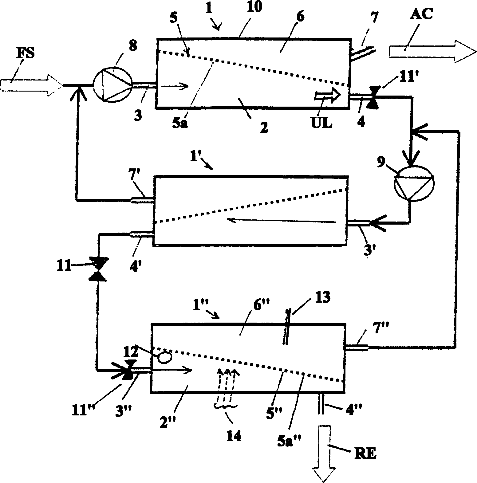
[0044] attached figure 1 A three-stage screening device is shown, using continuously arranged screens 1, 1', 1" according to the invention to clean slurry suspensions. These three screens are of similar design, which will 1. The screen 1 for cleaning the slurry suspension FS has a separation chamber 2 delimited by a housing 10 with a slurry suspension inlet 3 and a reject outlet 4. The slurry suspension FS is delivered to the separation chamber 2 by the pump 8 through the slurry suspension inlet 3. In the separation chamber 2, through a partition wall 5 with a screen structure 5a, one with a pointing The receiving chamber 6 of the upper receiving outlet 7 is separated from the slurry suspension inlet 3 and the waste outlet 4. The partition wall 5 asymmetrically separates the separation chamber 2. The slurry suspension high-speed flow onto the screen structure 5a, where part of the suspension is squeezed through the screen structure 5a and is separated in the process, so that ...


PUM


Abstract

In a paper making process a sorting assembly removes foreign bodies from a fibrous suspension. The assembly has a separation chamber with a suspension inlet, a clean suspension outlet, and a discharge for foreign bodies. The separation chamber is sub-divided into two by a sieve. The sieve is profiled on the suspension inlet and reject material side. The profiled sieve sets up vortices in the incoming suspension. The sieve surface may be flat, cambered or corrugated with peaks and troughs of between 0.3 and 1.5 mm. The sieve is a perforated plate with slits. The incoming suspension impinges on the slots at an angle of between 70 and 110 degrees. The plate may be sheet metal, ceramic or plastic and bears an anti-wear coating. Also claimed is a multi-stage sorting assembly.

Description

field of invention [0001] The invention relates to a screen for cleaning stock suspensions according to the preamble of claim 1 . technical background [0002] Screens are machines used in the paper industry to clean stock suspensions containing water, fibers and dirt particles. Here, the stock stream is fed through a screening device where a receiving stream containing water and fibers flows through a screen. A part of the flow called the reject flow, containing water, fibers and dirt particles, is removed in its entirety at the end relative to the feed flow. In this way, the screen separates the solid particles suspended in the water. In contrast, the filtration process separates liquids from solids. [0003] In general, screens of this type have an axially symmetrical design and consist of a housing with a slurry feed opening, a cylindrical screen support, usually with perforations or vertical slots, and a rotating rotor. This rotor is responsible for keeping the slot...

Claims


Application Information

Patent Timeline
Patent Type & Authority Applications(China)
IPC IPC(8): D21D5/02D21D5/04
CPCD21D5/02D21D5/04
Inventor 海尔穆斯·加布尔
Owner ANDRITZ AG
Why Eureka
Try Eureka