
Drying device

A technology of drying device and drying chamber, which is applied in the direction of drying gas arrangement, washing device, household cleaning device, etc., and can solve problems such as air turbulence, increased operating costs, and difficulty in uniform drying

Inactive Publication Date: 2005-05-18
KAISANBUTSUNO KIMURAYAKK
View PDF1 Cites 9 Cited by
  • Summary
  • Abstract
  • Description
  • Claims
  • Application Information

AI Technical Summary

Problems solved by technology

[0004] The drying device of the structure shown in the above-mentioned gazette, owing to making the inside of the hollow air supply part as a direct air passage, the air sucked from one drying chamber is sent into the other drying chamber, except from the periphery forming the air passage. In addition to more heat dissipation from the side wall, air turbulence is likely to occur in the air supply chamber, and it is difficult to evenly supply air to multiple drying chambers in a rectified state.
[0005] In addition, with the above-mentioned structure, if the storage part is constructed as a multi-layer wide structure and many boots are dried at the same time, it is difficult to dry evenly because the drying time of each boot varies greatly.
If all boots and shoes are fully dried, there is a problem of increasing operating costs

Method used


Image

  • Drying device
  • Drying device
  • Drying device

Examples


Embodiment Construction

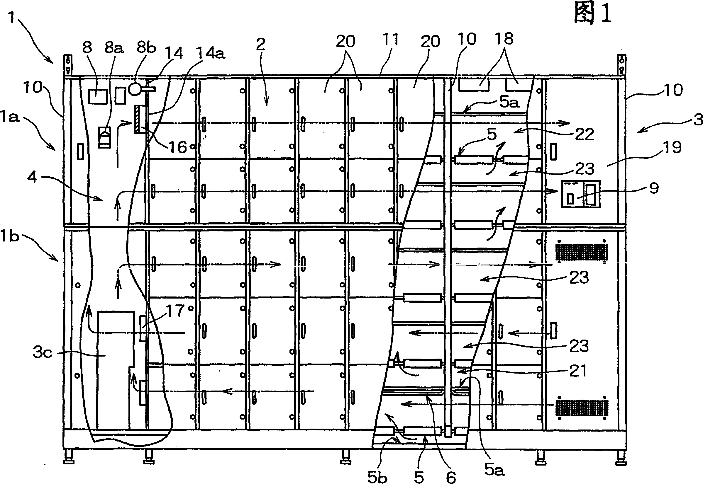
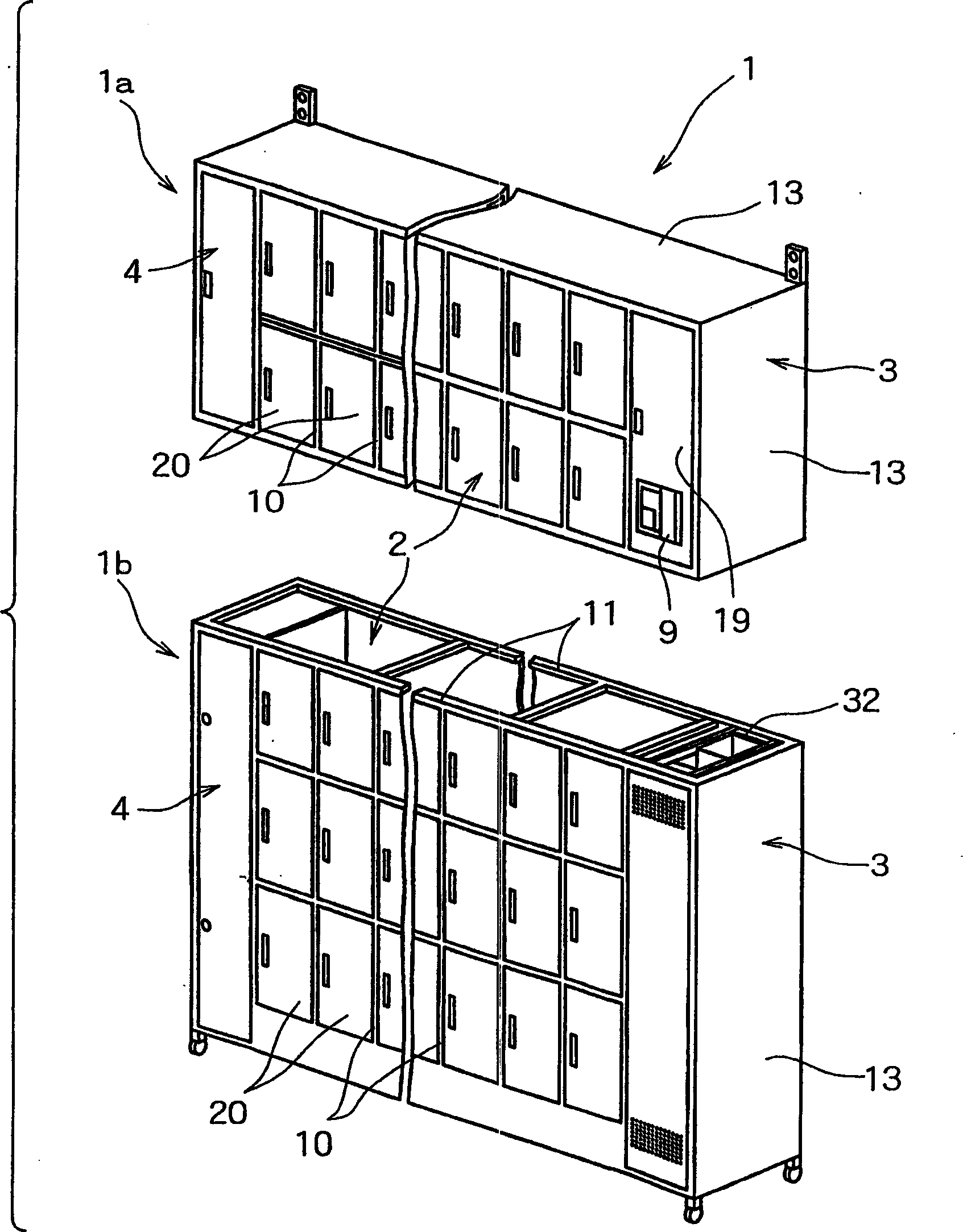
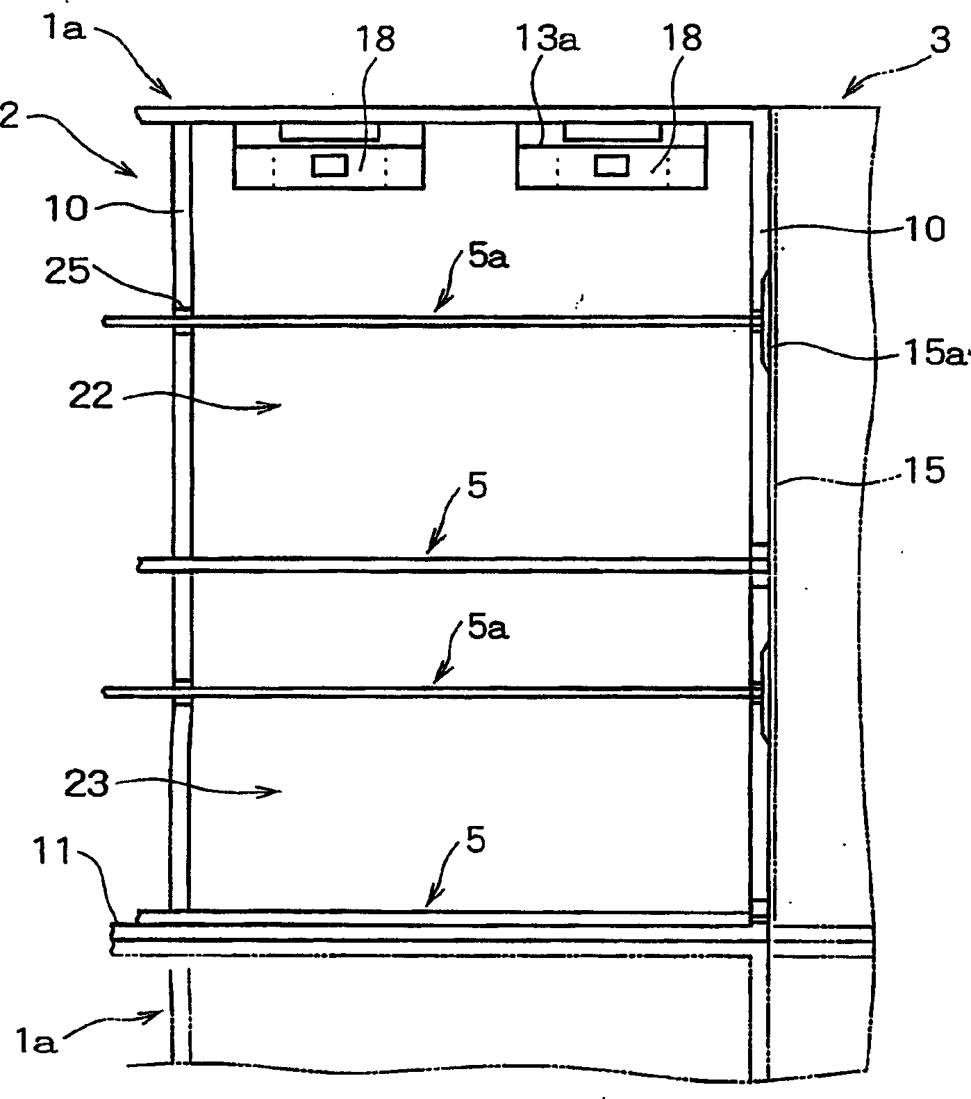
[0034] An embodiment of the present invention that is used for drying boots is described below according to accompanying drawing. Reference numeral 1 is a drying device of the present invention, and the drying device shown in FIG. 1 has a storage unit 2 and a blower unit 3 . The aforesaid storage part 2 is in the shape of a hollow chamber, and the storage part 2 is used for accommodating and drying a plurality of boots W as objects to be dried in pairs. Use: the aforementioned blower unit 3 is arranged on one side (right side) of the aforementioned storage unit 2 to send dry air into the storage unit 2 . Drying device 1 also is provided with blower guide part 4 in the up-down direction on the other side (left side) of aforementioned storage part 2, and this blower guide part 4 turns the air in the storage part 2, passes in the storage part 2, and Make it circulate on the air blower 3 side.

[0035] The drying device 1 of this embodiment, as figure 2 As shown, the above-ment...


PUM


Abstract

The present invention is a drying device (1) having a storage part (2), an air blowing part (3) and a heating part (3b). The above-mentioned storage part (2) forms the drying chamber that can be taken out to store the dried object into multiple layers; the above-mentioned air supply part (3) sends the air in the above-mentioned storage part (2) laterally from one side to the other side to make it Circulation: the aforementioned heating part (3b) heats the air circulating in the storage part (2). Above-mentioned blowing part (3) is formed the blowing chamber (30) of hollow up and down direction; In this blowing chamber (30) simultaneously, be set to be used for forming the air that heating part (3b) is heated and dry from either side up and down. The chamber side is sent to the blower (7) of the independent tubular air path (71) of the drying chamber on the other side. A heating unit (3b) is provided inside the blower tube (7), and a blower fan (32) is provided on the upstream side of the blower tube (7). The accommodating part (2) and the blower part (3) are divided and formed on the side of the upper body (1a) and the side of the lower body (1b).

Description

technical field [0001] The present invention relates to a drying device that removably accommodates clothing such as boots and clothes, and drying objects such as cooking utensils in a storage unit for drying. Background technique [0002] In the prior art, a drying device that removably accommodates and dries many boots as objects to be dried in a multi-layered storage section with a drying chamber having a door and a shelf is known in Japanese Patent Publication A drying device having the structure shown in JP-A-11-30479. [0003] The drying device is constituted as follows: a hollow air blower with an air suction fan and a blower fan is installed on one side leading to each drying chamber, and at the same time, a blower is installed on the other side to send the air sent into the drying chamber to the other side for drying. The air-sending guide part on the room side heats the air circulating in the storage part with the heating part. [0004] The drying device of the s...

Claims


Application Information

Patent Timeline
IPC IPC(8): A47L15/48A47L23/20D06F34/26D06F58/10F26B9/00F26B9/06F26B21/02F26B25/00F26B25/06
CPCA47L23/205D06F58/10F26B9/06F26B21/02F26B25/00F26B25/06D06F34/26
Inventor 木村隆行
Owner KAISANBUTSUNO KIMURAYAKK
Learn More