
Laying system for floor tiles

A technology for flooring and slate, which is applied to paving, floors, roads and other directions paved with prefabricated blocks. cost reduction effect

Inactive Publication Date: 2005-05-18
CLICKN WALK
View PDF2 Cites 6 Cited by
  • Summary
  • Abstract
  • Description
  • Claims
  • Application Information

AI Technical Summary

Problems solved by technology

This kind of laying is quite labor-intensive in terms of the required tools and required materials and also requires workers to have considerable manual skills
Also, it takes a long time before being able to step on the pavement
Another disadvantage is that the properly installed floor covering cannot be dismantled smoothly, that is, without damaging the floor.

Method used


Image

  • Laying system for floor tiles
  • Laying system for floor tiles
  • Laying system for floor tiles

Examples


Embodiment Construction

[0032] The illustrated embodiments are all based on a floor covering, which is composed of a number of rows of stone slabs, such as granite slabs, which are laid floating on a foundation, such as a rough cement floor or a wooden floor, with a spaced joint in the middle. on the floor.

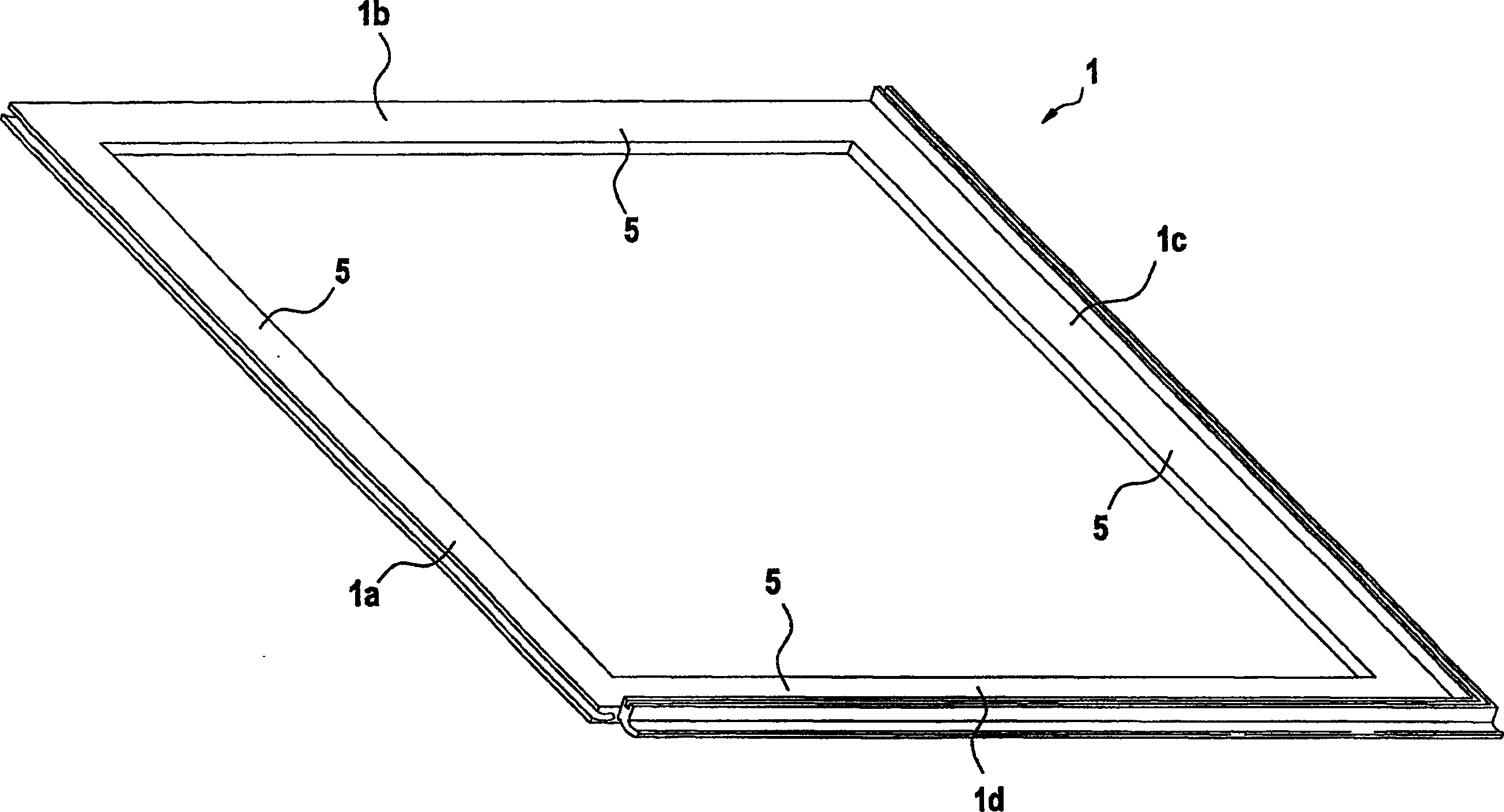
[0033] figure 1 In one view, a quadrilateral frame 1 for supporting a slab (not shown in the figure) such as a granite slab is shown. The frame 1 is made of plastic and is prefabricated. It can be an integral injection-molded part or some parts, which are composed of an extruded profile. Recycled plastics can also be used as raw materials.

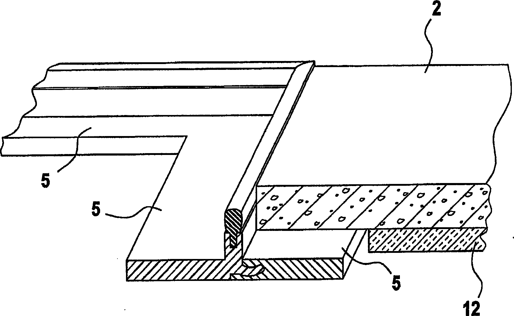
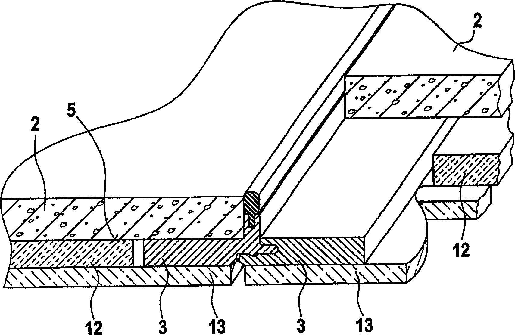
[0034] Among the four frame edges 1a-1d of the frame 1, the two adjacent frame edges 1c and 1d have one such as Figure 4 The cross-sectional view of the special-shaped plug-in part 3 is shown. The other two frame edges 1a and 1b have one such as Figure 5 The cross-sectional view shows the special-shaped plug-in part 4. The four frame edges 1a-1d have a strip...


PUM


Abstract

The invention relates to a paving system for tiles, especially flagstones, for paving ceilings, walls, or floors, in which each tile is provided with a paving frame on which the tile rests over at least part of its area. The paving frames comprise, on each of two adjacent (intersecting) limbs, a fin for the accommodation of a rubber-elastic sealing profile that defines the width of the seam.

Description

Technical field [0001] The present invention relates to a floor laying system and is particularly suitable for ceramic tiles, natural stone tiles and wood boards. Background technique [0002] In the case of ceramic tiles or stone bricks, the floor is in principle laid on a correspondingly prepared foundation such as a plaster trowel with the aid of a suitable adhesive. Here, the joint width is mostly determined by inserting the joint cross ruler and These seams must be jointed afterwards. This laying is quite laborious in terms of the tools and materials required and also requires workers to have considerable manual skills. In addition, it takes a long time before the pavement can be stepped on. Another disadvantage is that the floor coverings laid in accordance with regulations cannot be disassembled smoothly, that is, without damaging the floor. [0003] It is known in wooden boards, such as parquet or laminated boards for floor coverings, where two intersecting board sides ar...

Claims


Application Information

Patent Timeline
Patent Type & Authority Applications(China)
IPC IPC(8): E01C5/00E04F13/08E04F15/02
CPCE01C5/001E04F13/0862E04F15/02194E04F15/02172E04F15/082E04F15/105E04F15/02011E04F15/02016E04F15/203
Inventor T·德拉 佩帕
Owner CLICKN WALK
Learn More