Engine casing and printer with locking mechanism
A technology for locking devices, printers, applied in the directions of printing devices, printing, typewriters, etc.
Inactive Publication Date: 2005-11-02
SEIKO EPSON CORP
2 Cites 5 Cited by
AI-Extracted Technical Summary
Problems solved by technology
[0007] However, since the locking device of the commodity sales recording device in the above-mentioned related art adopts a mechanical locking method using a key or the like, it is necessary to equip ea...
Method used
[0121] The material of the housing unit 30 and the cover 20 is a steel plate having a thickness of about 1 mm through antirust treatment. Alternatively, the available plate can also be a stainless steel sheet (or an equivalent material), as long as it has sufficient workability and strength. To enhance handling, the outer ridges of the cover 20 and housing unit 30 may be formed by bending and handling the sheet material to eliminate sharp edges and provide sufficient strength.
[0140] The shaft 77 is pushed in and secured to the plate 75. The pressing rod 76 is mounted on the end of the shaft 77 and the stop...
Abstract
To provide a printer with a locking mechanism which can prevent roll paper in a POS terminal and product sales registration equipment from being easily taken out from the outside.
Application Domain
TypewritersOther printing apparatus
Technology Topic
EngineeringRolling paper +1
Image
Examples
- Experimental program(1)
Example Embodiment
[0104] Embodiments of the present invention will be described in detail below with reference to the accompanying drawings.
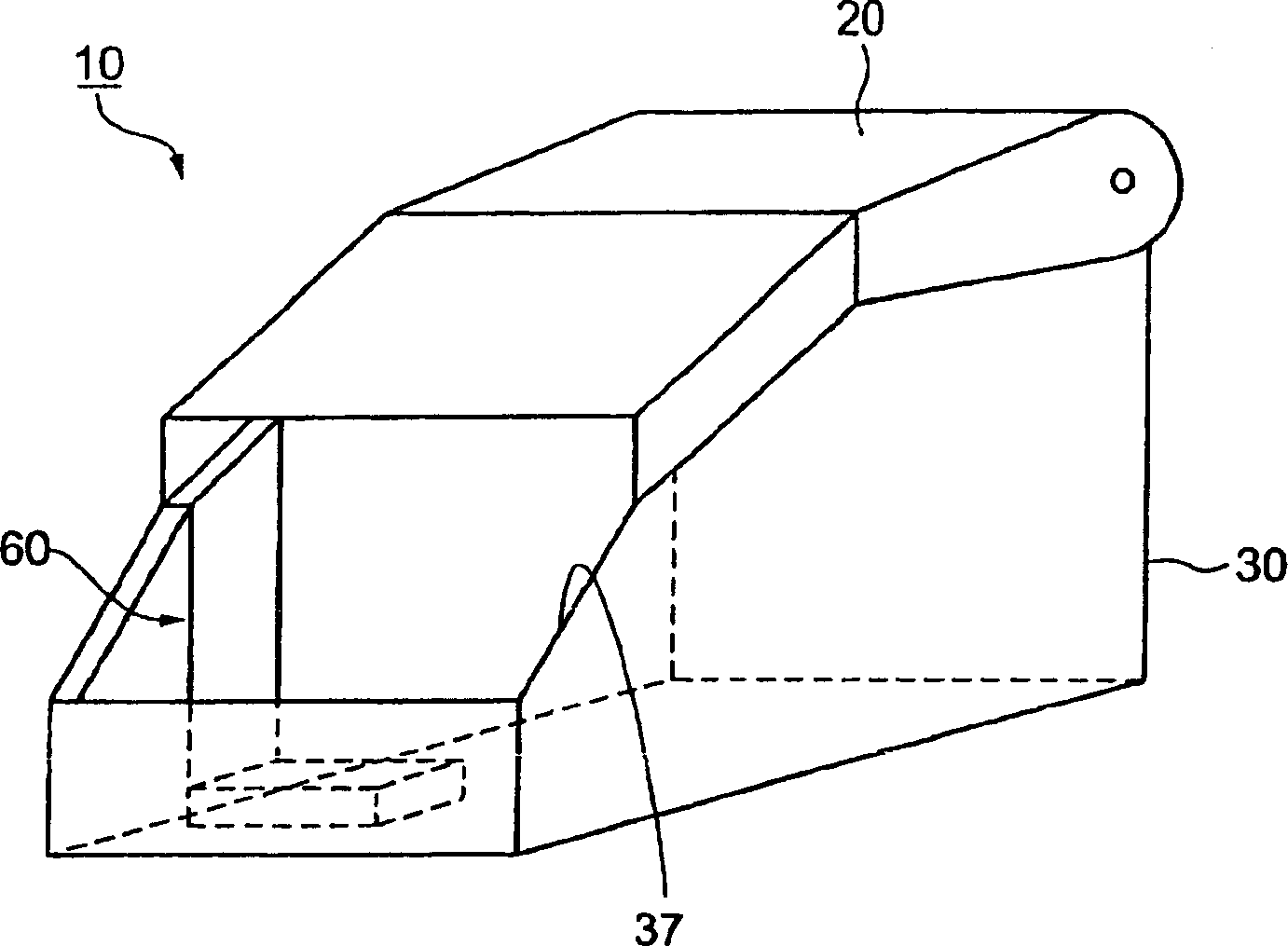
[0105] like figure 1 As shown, the housing 10 according to the first embodiment includes a housing unit 30 having an opening 37 and capable of accommodating contents, a lid 20 openably connected thereto capable of at least partially covering the opening 37, and connecting the lid 20 to the housing The body units 30 are mutually locked by the locking device 60 in the closed state. When locked after the lid 20 is closed, the locking device 60 confines the contained contents in the housing unit 30 . The locking device 60 is unlocked by an electric signal.
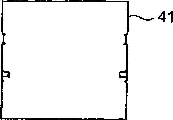
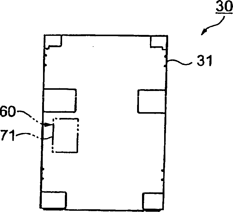
[0106] like Figure 2A As shown to 2C, the housing unit 30 includes a bottom panel 31 , a rear panel 41 and a side panel 51 . The locking device 60 includes a locking member 61 and an electromagnetic actuator 71 operated by an electrical signal. The locking member 61 is connected to the side panel 51 , and the electromagnetic actuator 71 is connected to the bottom panel 31 . Details of the locking device 61 will be described below.
[0107] As shown in FIG. 2C, the side panel 51 includes a central front panel 51, and the panels 53a and 53b have cover connecting portions 56a and 56b, respectively, and are connected to the front panel 52 from both sides. The housing unit 30 is generally in the shape of a generally rectangular parallelepiped and has an upper opening 37 . The housing unit 30 is formed by connecting the side panel 51 to the bottom panel 31 after bending the side panel 51 along the line, and then connecting the rear panel 41 to the bottom panel 31 and the panels 53a and 53b.
[0108] As shown in FIGS. 3A to 3D, the bottom panel 31 is a tray-shaped member obtained by bending along the edge portion. The bottom panel 31 has four fixing portions 32a, 32b, 32c and 32d at the front two corners and at positions slightly deviated from the center of the longer side line to the rear side in plan view 3A, on which the contents can be fixed. The bottom panel 31 also has fixing portions 33a and 33b at the rear two corners, on which the rear panel 41 is fixed. The fixing portions 32a, 32b, 32c, 32d, 33a and 33b extend inwardly from the bent edge portions to form a bracket shape.
[0109] Holes 32a, 32e, 32f, 32g, and 32h for tightening the contained items are formed through the top flat portions of the four fixing portions 32a, 32b, 32c, and 32d, so that when from Figure 3C They are symmetrical with respect to the center when viewed in the direction of (that is, from the left). Likewise, holes 33c and 33d for screwing the rear panel 41 are formed through the top flat portions of the two fixing portions 33a and 33b with which the rear panel 41 is fixed. like Figure 3B-3D The large holes 32i, 32j, 32k, 32l, 32e and 33f into which a tightening tool such as a screwdriver can be inserted are formed through the bottom plate directly below the corresponding six holes 32e, 32f, 32g, 32h, 33e and 33f as shown in the side view of .
[0110] Four screw holes 34a, 34b, 34c and 34d for fixing the side panel 51, four screw holes 35a, 35b, 35c and 35d for fixing the electromagnetic actuator 71, one bearing hole 38 and four The holes 36a, 36b, 36c and 36d for securing the assembled casing 10 with the locking device to a certain position are formed through the bottom plate at corresponding positions.
[0111] like Figures 4A to 4C As shown, the rear panel 41 is a member in the shape of the letter L with a curved portion 42 at the top. The rear panel 41 is formed with support portions 43a and 43b for supporting the rotation shaft of the cover 20, and hooks 44a and 44b, which are both bent to protrude in the same direction.
[0112]Shaft holes 43c and 43d for supporting the rotating shaft are formed through the ends of the two supporting portions 43a and 43b, respectively. Holes 44c and 44d for fixing the side panel 51 are formed through the two hooks 44a and 44b, respectively. The bottom plate 48 forms part of the shape of the letter L when viewed from the side and has notches 46a and 46b and fixing holes 45a and 45b so that the rear panel 41 can be fixed to the side panel 41 to avoid the fixing portion 33a on the bottom panel 31 and 33b.
[0113] like Figure 5A As shown in 5D, the two panels 53a and 53b on the side panel 51 are connected to the front panel 52 to form a bracket shape in plan view. On the side panel 51, four fixing portions 54a, 54b, 54c, and 54d for fixing to the bottom panel 31 are bent inward.
[0114] The two panels 53a and 53b are formed with connecting portions 56a and 56b for connecting the cover 20, respectively. The connecting portions 56a and 56b are retracted inwardly by a length equal to the thickness of the plate at the portion overlapping the lid 20 . Axle holes 58a and 58b are formed through the connecting portions 56a and 56b, and arc-shaped long holes 58c and 58d are formed through the connecting portions 56a and 56b at positions on a circle with the shaft holes 58a and 58b as centers. Two fixing holes 59a and 59b for fixing the rear panel 41 are formed through the panels 53a and 53b at positions near their rear ends, respectively.
[0115] Four fixing holes 55a, 55b, 55c and 55b for fixing the locking member 61 are formed through the panel 53a. The beam 57 protrudes inwardly so that the locking member 61 to which it is connected cannot be seen from the front panel 52 side.
[0116] As shown in FIGS. 6A to 6D, the two cover support portions 21a and 21b (side panels) of the cover 20 are penetrated by fixing holes and bent in the same direction so that the cover 20 conforms to the shape of the side panel 51. The cover 20 has a hook 22 near the front end with a rectangular hole 22a. The hook 22 engages with the locking member 61 of the housing unit 30 to keep the lid 20 in a closed state.
[0117] As shown in FIG. 6A, shaft holes 24a and 24b are formed through the two cover support portions 21a and 21b, respectively. Also, the cover supporting portions 21a and 21b are formed with inwardly facing protrusions 25a and 25b at positions of circles corresponding to the long holes 58c and 58d passing through the side panel 51 (see Figure 5C and 5D) of the lid connecting portions 56a and 56b are formed. The hooks 26a and 26b extend from the peripheries of the cover support portions 21a and 21b, and are bent inward in a ladder shape.
[0118] The protrusions 25a and 25b cooperate with the long holes 58a and 58b, respectively, to limit the opening/closing angle of the cover 20. The two hooks 26a and 26b allow the springs to stretch between themselves and the hooks 44a and 44b of the rear panel 41 to push the lid 20 in the opening direction.
[0119] In addition, two protrusions 27a and 27b extend from the peripheries of the cover supporting portions 21a and 21b. The protrusions are bent inward, and the peripheral portion of the top plate 28 of the cover 20 is bent. The cover supporting portions 21a and 21b and the top plate 28 are fixed to each other.
[0120] The side panels 22 of the lid 20 are provided with hooks 22, said side panels are formed with a wider portion 23 which is retracted inwardly by approximately the same length as the thickness of the panel, so that when the lid 20 is closed, the side panel 51 The outer surface of the panel 53a is parallel, and the hook 22 is reliably guided to the locking member 61.
[0121] The material of the case unit 30 and the cover 20 is a steel plate having a thickness of about 1 mm which has undergone anti-rust treatment. Alternatively, stainless steel sheets (or an equivalent material) can be used as long as they have sufficient workability and strength. To enhance handling performance, the outer ridges of the cover 20 and housing unit 30 may be formed by bending the sheet and handling the sheet to eliminate sharp edges and provide sufficient strength.
[0122] The design of the enclosure 10 with the locking device is not limited to the method disclosed in this embodiment. Moreover, the cabinet 10 can also be designed according to the size and shape of the object to be accommodated, and can also be designed according to the part locked in the closed state by the cover 20 .
[0123] Next, an assembling method of the cabinet 10 with the locking device will be described.
[0124] First, an electromagnetic actuator 71 (described in more detail below) is screwed to certain locations on the bottom panel 31 from above.
[0125] Then, the fixing portions 54a, 54b, 54c, and 54d of the side panel 51 are inserted into the notches of the longer side portions of the bottom panel 31 and screwed to the bottom panel 31 from the inside with the screw holes 34a, 34b, 34c, and 34d. Then, the bottom plate 48 of the rear panel 41, which forms part of the letter L, viewed from the side, is screwed to the fixing portions 33a and 33b of the bottom panel 31 by inserting screws into the holes 33e and 33f passing through the bottom panel 31. The bottom plate is formed.
[0126] The rear panel 41 passes through the handle shaft 81 (see Figure 7A ) into the holes 44c and 44d of the hooks 44a and 44b and the fixing holes 59a and 59b of the side panel 51, and put the stop ring in the shape of the letter E into the groove 81a inside the assembled housing unit 30 The way is fixed on the side panel 51 .
[0127] A locking member 61 (explained in more detail below) is then secured to a location on the inner surface of the panel 53a. The housing unit 30 is thus completed.
[0128] Then, the cover 20 as shown in FIG. 6 is attached to the housing unit 30 . For connection, the cover 20 is connected so that the cover support parts 21a and 21b cover the cover connecting parts 56a and 56b of the side panel 51 and the top plate 28 covers the curved part 42 of the rear panel 41 .
[0129] As for the fixing method, the cover 20 is fixed by inserting the shaft 81 into the left-hand shaft holes 24a, 58a and 43c and the right-hand shaft holes 24b, 58b and 43d, and inserting the stop ring in the shape of the letter E into the housing unit 30 It is realized in the inner groove 81a in which the shaft hole is formed through the cover supporting parts 21a and 21b, the cover connecting parts 56a and 56b and the supporting parts 43a and 43b of the rear panel 41. The springs are stretched between the hooks 26a and 26b of the cover support parts 21a and 21b and the hooks 44a and 44b of the rear panel 41 . This completes the casing 10 with the locking device 60 .
[0130] With the above-described assembling method of the cabinet 10 with the locking device, in order to disassemble the cabinet 10 that has been assembled, the cover 20 is opened and the screw is loosened through the opening 37 .
[0131] In order to remove the cover 20, it is necessary to remove the stop ring in the shape of the letter E and pull out the shaft 81 from the inside of the housing unit 30, and remove the stop ring in the shape of the letter E and pull out the shaft 81 by the same method to remove the rear The panel 41 and the side panel 51 are separated from each other.
[0132] Therefore, it is difficult to remove the cabinet 10 with the locking device from the outside in a state in which all components are installed and filled and fixed in the opening 37 of the case unit 30 of the cabinet 10 and the cover 20 is closed and locked.
[0133] Similarly, the locking device 60 is provided in the housing unit 30 so that it is impossible to directly contact the locking device 60 from the outside of the cabinet 10 . Therefore, the cabinet 10 cannot be opened from the outside.
[0134] The lid 20 is urged in the opening direction by springs stretched between the hooks 26a and 26b of the lid support portions 21a and 21b and the hooks 44a and 44b of the rear panel 41 . Therefore, if the locking device 60 is unlocked, the cover 20 is opened within the range allowed by the long holes 58c and 58d of the cover connecting portions 56a and 56b, and then the cover 20 is braked. As long as the lid 20 is closed and locked, it will not open. Thus, one can recognize when the lid 20 is locked.
[0135] Below, will refer to Figures 8A to 8C The locking device 60 is described in detail.
[0136] like Figure 8A As shown, the locking member 61 is attached to the inner surface of the panel 53a of the side panel 51 . The locking member 61 includes a rotating hook 62 engaged with the hook 22 of the cover 20, a lever 63 for stopping the rotation of the rotating hook 62 at a certain angle to maintain the locked state with the hook 22, and a lever 63 fixed to the inner surface of the panel 53a 64 on the brake. The rotating hook 62 and the lever 63 are rotatably supported on the inner surface of the panel 53 through shafts 66a and 66b, respectively.
[0137] The swivel hook 62 is formed with a claw 62b and a hook 62c that are inserted into the hole 22b of the hook 22, and a spring 65a capable of pushing the swivel hook in the unlocking direction is hooked on the hook female 2c, and when the swivel hook 62 rotates in the unlocking direction The protrusion 62 d that can stop the rotation of the rotating hook 62 by pressing against the stopper 64 .
[0138] A hook 63b is formed at one end of the lever 63, and a spring 65b capable of urging the lever 63 in the closing rotation direction around the shaft 66b is hooked on the hook 63b. The other end of the lever 63 is formed with a notch 63a for receiving the stopper 62a of the rotating hook 62 . The end with the hook 63b also has an inwardly curved retainer 63c.
[0139] like Figure 8B As shown, the electromagnetic actuator 71 includes a solenoid (electromagnetic switch) 72 responsive to an electrical signal to urge and retract the plunger 73 to the closed or open position, supported by a shaft 77 (see Figure 7B ) is supported by a pivot, an L-shaped pressure rod 76 with one end and the end of the plunger 73 assembled together, and a plate 75 connected to the above-mentioned components.
[0140] The shaft 77 is pushed in and fixed to the plate 75 . The pressing rod 76 is mounted on the end of the shaft 77 , and the stop ring in the shape of the letter E is put into the groove 77 . The pressure lever 76 is pivotally supported by the shaft 77 . The plate 75 has a pin 74 on which one end of the spring 65b is fixed. The plate 75 also has a stopper 75a formed by bending a portion of the plate 75 to prevent excessive rotation of the pressure lever 76 when it is rotated in the closing direction.
[0141] The operation of the above-mentioned locking device 60 will be described in detail below.
[0142] When the cover 20 is lowered to close the housing unit 30 , the hooks 22 formed at the ends of the cover 20 push the tops of the claws 62 b of the rotating hooks 62 . The pawl 62b eventually engages with the hole 22a of the hook 22 .
[0143] At this time, the rotating hook 62 is forced to rotate in the opening direction because it is urged by the spring 65a. However, since the lever 63 is urged toward the closing direction by the spring 65b, the notch 63a of the lever 63 receives the stopper 62 of the rotating hook 62, so that the locking member 61 is locked to the closed state.
[0144] When the locking member 61 is locked, the presser 63c formed at the end of the rod 63 is stopped in a state of pushing the pressing rod 76 of the electromagnetic actuator 71, and the end of the plunger 73 is thereby pulled out. At the same time, the spring 65b pushes the presser 63c to maintain this state.
[0145] In order to open the locking member 61, the solenoid 71 is operated by an electrical signal, thus returning the plunger 73 that is pulled out.
[0146]When the plunger 73 is returned, the pressing rod 76 pushes the presser 63c of the rod 63 . In this way, the lever 63 is disengaged from the stopper 62a of the rotary hook 62, and the rotary hook 62 is urged to rotate in the opening direction by the spring 65a. The claws 62b are separated from the holes 22a of the hooks 22 of the cover 20, and the cover 20 is opened.
[0147] When the lid 20 is opened, the rotating hook 62 is rotated toward the opening direction, and since it is urged by the spring 65a, the protrusion 62 abuts the stopper 64 and is thus stopped. At this time, the notch 63a of the lever 63 is stopped in a state where it does not come into contact with the stopper 62a of the rotating hook 62 . The ready state is maintained until the lid 20 is closed again.
[0148] As long as the solenoid 72 is used, the locking device 60 is not limited to the solution adopted in this embodiment. For example, the locking member 61 which is unlocked by directly transmitting the operation of the plunger 73 by the solenoid 72 to the rotating hook 62 is not limited to this example. Also, the device that pushes the lid 20, the rotating hook 62 and the rod 63 may be a cylinder or the like that seals air or gasoline inside.
[0149] A printer equipped with the above-described cabinet with a locking device will be described below.
[0150] like Figure 9A As shown, the printer main body 110 is equipped with: an ejection opening 112 through which the printed portion of the roll paper (print medium) 116 can be ejected; and a printer cover 111 as a cover, which can cover the combined roll paper 116 without covering the ejection opening 112; the open button 113 as a cover operating part is used to open the closed printer cover 111, and the roller 125 connected with the printer cover 111, which can be used as a feeding part for ejecting a part of the roll paper 116; A motor (not shown) for driving (rotating) the drum 125; a feed button 114 for activating the drum 125; and an indicator light 115 indicating the status of the printer body 110.
[0151] like Figure 9B As shown, the printing device 120 of the printer main body 110 is equipped with a roll paper support frame 122 capable of engaging the roll paper 116 into the main body frame 123 and a roll paper cover 121 installed inside the printer cover 111 which can be closed from above Hold the roll paper 116. In addition, the thermal print head 124 urged by the spring 130 is installed at a position opposite to the drum 125 , and the automatic paper cutting unit 126 is installed under the ejection opening 112 .
[0152] The operation of the printing apparatus 120 is as follows. Printing is performed when the roller 125 presses a portion of the thermal recording roll paper 116 against the print head 124 . At the same time, the roller 125 conveys a part of the roll paper 116 in the ejecting direction D. After the printing operation is completed, a portion of the roll paper 116 is cut by being placed between the movable blade 128 driven by the motor 127 of the automatic cutting unit 126 and the fixed blade 129 on the printer cover 111 side.
[0153] By using the printer main body 110 having the above-described printing device 120, it is possible to print, for example, a certificate of value, a train ticket or a ticket, a receipt equivalent to a sales ticket, or a similar ticket valid after drawing information, And give the ticket to the customer.
[0154] Although in this embodiment, the printer body 110 is of a thermal type and the printing medium is a thermal recording roll paper 116, it may be a needle type, ink jet type, laser type or the like on a roll of recording paper, A printer main body that performs drawing on a separate sheet of recording paper or the like.
[0155] As shown in FIGS. 10A and 10B , the printer with locking device 100 according to the present embodiment includes a cabinet with locking device 10 and a printer main body 110 placed in the cabinet with locking device 10 . The printer main body 110 is a printer that receives recording information and performs recording on the sucked roll paper 116, and has: an ejection opening 112 from which a recorded portion of the roll paper 116 is ejected; The printer cover 111 of the outlet 112; the open button 113 for opening the printer cover 111 from the closed state;
[0156] The printer 100 with the locking device is put into the housing unit 30 of the casing 10 with the locking device 60 described above, and the cover 20 is locked with the housing unit 30 so that the printer cover 111 , the open button 113 and the feed button 114 Covered by the cover 20, the printer cover 111 is closed.
[0157] The method of placing the printer main body 110 in the cabinet 10 with the locking device is as follows. When the cover 20 is opened, the printer main body 110 is inserted through the opening 37 and placed on the fixing portions 32 a , 32 b , 32 c and 32 d of the bottom panel 31 .
[0158] The printer main body 110 is formed by inserting screws 118 into large holes 32i, 32j, 32k and 32l formed through the bottom plate of the bottom plate 31, and tightening the screws 118 to screw holes (not shown) formed on the bottom of the printer main body 110. , so as to be fixed on the bottom panel 31 .
[0159] In order to mount the printer having the locking device and having the cabinet 10 with the locking device to a specific location, such as a workbench, the cabinet 10 can be fixed to the The locking device is fixed on the table.
[0160] like Figure 11 As shown, the printing system 200 includes: a printer body 110 accommodated in a casing 10 with a locking device, a computer host (hereinafter referred to as a host) connected to the printer body through a signal line 203, belonging to the casing with a locking device Electromagnetic actuator 71 which is part of locking device 60 of 10, and drawer (money box) 202 near cabinet 10 with locking device.
[0161] The printer body 110 includes a transmitter 117 capable of transmitting an electrical signal for opening the drawer 202 . Transmitter 117 has two output systems. One output system is connected to the drawer 202 through the signal line 203, and the other output system is connected to the solenoid 72 of the electromagnetic actuator 71 in the casing 10 with the locking device through the signal line 203. The printer main body 110 receives power from the outside to perform line operations.
[0162] When an input operation is performed on the host computer 201, the host computer 201 transmits recording information to the printer main body 110, an instruction signal to open the drawer 202, or the like.
[0163] If the host 201 sends an unlock command signal to open the drawer 202 (in which the output system of the transmitter 117 connected to the electromagnetic actuator 71 is specified), the transmitter 117 sends the unlock signal to the solenoid 72 of the electromagnetic actuator 71, The solenoid 72 opens the locking member 61 , that is, the lid 20 is opened from the housing unit 30 .
[0164] Similarly, if the host 201 sends an unlock command signal to open the drawer 202 (in which the output system of the transmitter 117 connected to the drawer 202 is specified), the transmitter 117 sends the unlock signal to the drawer 202 . In this way, the drawer 202 can be opened. Those skilled in the art will understand that the unlocking instruction signal sent from the host 201 to the printer body 110 is not limited to an electrical signal, but can also be a command or other manners.
[0165] In order to lead out the signal line 203 connecting the printer main body 110 (installed in the cabinet 10 with the locking device) and the main body 201 and the drawer 202, a rear panel 41 of the cabinet 10 with the locking device is formed with a minimum necessary size holes (not shown). Although the printing system 200 according to the present embodiment is provided with the drawer 202 when the printing system 200 is used as a POS system, the drawer 202 is not necessary, for example, when no cash is exchanged.
[0166] The first embodiment described above provides at least the following advantages:
[0167] (1) In the cabinet 10 with the locking device, when the cover 20 is closed, the hook 22 of the cover 20 is engaged with the locking member 61 . In this way, the cover 20 and the case unit 30 are mutually locked in a closed state with the printer body 110 being accommodated and fixed in the case 30 .
[0168] Since the electromagnetic actuator 51 is equipped with a solenoid 72 that opens the locking member 61 in response to an electrical signal, the person in charge of the system, such as (but not limited to), need not have access to the housing with the locking device 10 and open the cover 20 , that is, by sending the first electrical signal from the host 201 to the printer body 110 .
[0169] Therefore, it is possible to perform remote control, and it is also possible to prevent a third person from taking out the printer main body 110 from the cabinet 10 with the locking device without authorization.
[0170] (2) Once the lid 20 and the housing unit 30 are mutually locked in a closed state, the locking member 61 cannot be opened unless the solenoid 72 of the electromagnetic actuator 51 is operated by an electric signal. Therefore, the closed state can be maintained even if the solenoid 72 fails.
[0171] (3) The locking device 60 includes the locking member 61 and the electromagnetic actuator 71 , both of which are placed in the housing unit 30 . Therefore, once the cover 20 and the housing unit 30 are mutually locked in the closed state in the state where the printer main body 110 is accommodated in the housing unit 30 , an attempt to perform unauthorized unlocking from outside the housing 10 by breaking the locking device 60 behavior can be prevented. That is, it is possible to prevent the printer main body 110 from being easily removed from the cabinet 10 with the locking device.
[0172] (4) The printer 100 with the locking device and the housing unit 30 are locked together, so that the printer body 110 is placed in the housing 10 with the locking device, and the cover 20 is closed to cover the printer cover 111, Open button 113 and feed button 114 . Unless the locking device 60 is opened, the roll paper 116 placed inside cannot be taken out by opening the printer cover 111, or a part of the roll paper 116 cannot be ejected by pressing the feed button 114. This can prevent unauthorized removal of the roll paper 116 placed in the printer main body 110 .
[0173] (5) The electromagnetic actuator 71 , which is a part of the locking device 60 of the printer with locking device 100 , is connected to the transmitter 117 incorporated inside the printer main body 110 . When the printer main body 110 receives the unlock command signal from the host 201, the solenoid 72 of the electromagnetic actuator 71 is controlled by the unlock signal output from the transmitter 117, so that the locking member 61 is opened. That is, the cover 20 can be opened by remote control without directly touching the printer 100 with the locking device.
[0174] Of the two output systems of the transmitter 117 , the output system for the drawer 202 is used to transmit an unlock signal (second electrical signal) from the printer body 110 to the electromagnetic actuator 71 . In this way, it is possible to open the electromagnetic actuator 71 without adding a transmitter (including an output terminal) dedicated to unlocking to the printer main body 110 .
[0175] (7) The cover 20 is urged in the opening direction by the spring stretched between the hooks 26a and 26b of the cover supporting portions 21a and 21b and the hooks 44a and 44b of the rear panel 41 . Therefore, maintenance work such as replacing the roll paper 116 incorporated in the printer body 110 or removing a jammed portion of the roll paper 116 can be easily performed without supporting (eg, by hand) the opened cover 20 .
[0176] like Figure 12A and 12BAs shown, the printer 300 with a locking device according to the second embodiment of the present invention is that the above-described printer main body 110 is accommodated in a cabinet 308 with a locking device.
[0177] The casing 308 with locking means includes: a casing unit 304 having an opening 304a for accommodating the printer main body 110; a support frame (cover member) 301 that opens and closes in a range around the shaft 309, and a casing unit 301 provided in the casing Locking device 307 in unit 304.
[0178] The support frame 301 is in the shape of a bracket and includes a holder 303 and an arm 302 . One end of the arm 302 connected to the support frame 301 at both ends is supported by the inner surface of the housing unit 304 , that is, pivotally supported by the shaft 309 .
[0179] The case of the locking device 307 is as follows: Figure 8B The illustrated electromagnetic actuator 71 is provided on the bottom surface 305 of the housing unit 304 and one of the arms 302 is provided with a locking member substantially similar to the locking member 61 of the first embodiment. The support frame 301 is thus opened and closed.
[0180] A rear cover 306 is provided at the rear of the housing unit 304 . The rear cover 306 can cover the connector or the like to which the signal line or the like is connected, and when the printer main body 110 is placed in the housing unit 304, the signal line and the said signal line provided on the rear side of the printer main body 110. The connector 110 is connected.
[0181] The lockable printer 300 having the lockable enclosure 308 employs and Figure 11 The illustrated printing system 200 is generally similar to a printing system.
[0182] Therefore, if the printer body 110 is placed and fixed into the housing unit 304, and the support frame 301 is lowered to the front side, the support frame 301 covers a part of the printer cover 111, the open button 113 and the feed button 114 and the case The body unit 304 is locked in a substantially closed state.
[0183] To achieve unlocking, an input operation is performed on the host 201 (see Figure 11 ). The solenoid 72 of the electromagnetic actuator 71 is operated by an unlock signal (second electrical signal) output from the transmitter 117 incorporated in the printer body 110 according to an unlock command signal sent from the host computer 201 to the printer body 110 . In this way, the support frame 301 is opened.
[0184] The second embodiment provides at least the following advantages:
[0185] (1) In the printer 300 with a locking device, the printer main body 110 is placed in the casing 308 with a locking device, and the support frame 301 and the casing unit 304 are locked in a closed state while covering the printer cover 111 part, open button 113 and feed button 114. Thus, unless the locking device 307 is unlocked, the combined roll paper cannot be taken out by opening the printer cover 111 , or a part of the roll paper 116 cannot be ejected by pressing the feed button 114 . Therefore, it is possible to prevent the roll paper 116 incorporated in the printer main body 110 from being removed without authorization.
[0186] (2) The electromagnetic actuator 71 , which is part of the locking device 307 of the printer 300 with locking device, is connected to the transmitter 117 incorporated in the printer body 110 . When the printer main body 110 receives the unlock command signal from the host 201, the solenoid 72 of the electromagnetic actuator 71 is controlled by the unlock signal (second electrical signal) sent from the transmitter 117, so that the support frame 301 is opened. That is, the support frame 301 can be opened by remote control without directly contacting the printer 300 with the locking device.
[0187] The configurations of the first and second embodiments can be modified as follows:
[0188] The housing 10 with locking means can be retrofitted with a lid 20 which can almost completely cover the housing unit 30 except for the opening 37 having the necessary minimum area.
[0189] The enclosure 10 with locking device can be retrofitted with a housing unit 30, which may be a casting, a plastic part, or other similar components that are an integral part of the bottom panel 31, rear panel 41 and side panels 51.
[0190] The means for opening the locking member 61 may employ an electric motor or an actuator driven by electricity, compressed gas or other means.
[0191] The printer 100 with a locking device can be modified to be equipped with the cabinet 10 with a locking device having a cover 20 that can be locked in a closed state with the housing unit 30 and that, except for the ejection opening 112 of the printer body 110, can be provided. The printer body 110 is almost completely covered.
[0192] The printing system may be modified so that the electromagnetic locking unit 71 opens the locking member 61 by directly receiving the unlocking signal (second electrical signal) from the host computer 201 .
[0193] The cover 20 can be modified to cover only the printer cover 111 , which can prevent the roll paper 116 from being removed by opening the printer cover 111 . Specifically, this modification is effective enough even when the printer main body 110 is not equipped with the feed button 114 .
[0194] The cover 20 can only cover the printer cover 111 and the feed button 114 after being modified. This modification can prevent the roll paper 116 from being taken out by opening the printer cover 111 and can also prevent the roll paper 116 from being conveyed by pressing the feed button 114 .
[0195] A third embodiment of the present invention will be described below.
[0196] like Figure 13A As shown, the printer body 401 may be applied to, for example, but not limited to, a printer of a POS system or the like, and used to issue receipts. The printer main body 401 uses the print head 424 to perform printing on roll paper (print medium).
[0197] The printer main body 401 is provided with an ejection opening 412 through which a part of the roll paper 416 is ejected, and a printer cover 411 as a cover that covers the built-in roll paper 416 but does not cover the ejection opening 412, and is used to open the Open button 413 for closed printer lid 411, roller 425 to eject a portion of roll paper 416, motor (not shown) to drive roller 425, feed button 414 to activate roller 425, to instruct printer Indicator light 415 for the status of the main body 401, and locking device 460 for locking the printer cover 411 in the closed state (see Figure 14 ). A rear cover 401 a is provided at the rear of the printer main body 401 .
[0198] The printer main body 401 includes a casing main body 404 capable of accommodating roll paper 416 , an openable and closable printer cover 411 attached to the casing main body 404 , and a printing device 420 accommodated in the casing main body 404 .
[0199] like Figure 13B As shown, the printing device 420 is equipped with a roll paper support frame 422 capable of supporting the roll paper 416 from below, and a roll paper cover 421 capable of covering the roll paper 416 from above.
[0200] Also, the spring 430 provided in the main body frame 423 pushes the thermal print head 424 toward the cylinder 425 , so that the print head 424 can print on the roll paper 416 .
[0201] Printing is performed when the roller 425 presses a portion of the roll paper 416 against the print head 424. At the same time, the roller 425 feeds a part of the roll paper 416 in the ejecting direction D. As shown in FIG. When the printing operation is completed, a part of the roll paper 416 is placed between the movable blade 428 driven by the motor 427 of the automatic cutting unit 426 and the fixed blade 429 provided on the side of the printer cover 411 to be cut.
[0202] like Figure 14 As shown, the locking device 460 includes a lid frame 461 provided with an electromagnetic actuator 470 , and a lid lever engaged with the lid frame 461 .
[0203] The electromagnetic actuator 470 provided in the cover frame 461 is equipped with a solenoid 471 . The solenoid 471 is fixed to the cover frame 461 with screws 471b (FIG. 15A). The plunger 474 of the solenoid 471 and the unlocking lever 472 are engaged with each other by the spring pin 471a. The unlocking lever 472 is engaged with the shaft 473 protruding from the cover frame 461 .
[0204] The unlocking lever 472 can be rotated in the direction A about the axis 473 by attracting the plunger 474 in the direction indicated by the arrow. Locking is achieved when unlock lever 472 and cam 464 are engaged.
[0205] The shaft 467a is inserted into the cam hole 464b so that the cam 464 is supported. The portion of the cam hole 464b that engages with the shaft 467a has a cross section in the shape of a letter D, so that the cam 464 can be prevented from rotating.
[0206] The shaft 467a is fitted with E-rings (two E-rings in this example) so that the cam 464 does not come off in the axial direction and the engagement position of the cam 464 and the unlocking lever 472 does not deviate. The shaft 467a is supported by the bearings 462a and 462c so that the shaft 467a is rotatably supported.
[0207] The shaft 467a is inserted into the hole 469a of the cover rod 469 . Also, the portion of the hole 469a that engages with the shaft 467a has a cross-section in the shape of a letter D, so that the cover lever 469 can be prevented from rotating.
[0208] On the other hand, the shaft 467b is inserted into the hole 469b of the cover lever 469, and the shaft 467 is connected to the bearing 462b, so that the shaft 467b is rotatably supported. The shaft 467b is fitted with an E-ring so that it does not come off in the shaft direction.
[0209] The spring 465 is connected to the protrusion 472b of the unlocking lever 472, and the hook portion 465a of the spring 465 is connected to the shaft separation spring hook 466 provided on the cover frame 461. Spring 465 urges unlock lever 472 in the direction of ejection plunger 474 .
[0210] When the plunger 474 is attracted in the direction of the arrow by operating the solenoid 471 which is part of the electric unlocking device, the unlocking lever 472 is rotated in the direction A about the axis 473 . In this way, the unlocking lever 472 is separated from the cam 464, and unlocking is achieved. Conversely, when the plunger 474 is released, the unlocking lever 472 is rotated by the spring 465 in the direction opposite to the direction A, so that the unlocking lever 472 engages with the cam 464, thus achieving locking.
[0211] Next, the assembly sequence of the locking device 460 will be described with reference to the exploded perspective view 15A.
[0212] First, the solenoid 471 is fixed to the cover frame 461 with screws 471b. Then, the shaft 473 is inserted into the hole 472c of the unlocking lever 472 and fitted with the E-ring 468 .
[0213] Then, the plunger 474 is installed relative to the unlocking lever 472, and the spring pin 471a is inserted into the hole 472d, so that the plunger 474 and the unlocking lever 472 are engaged with each other.
[0214] Then, the spring 465 is hooked to the protrusion 472b and the shaft separation spring hook 466 . Subsequently, the hole 469a and the bearing 462a of the cover rod 469 are positioned relative to each other, and the hole 469b and the bearing 462b are positioned relative to each other. Shaft 467a is inserted into bore 469a and bearing 462a and mounted with E-ring 468.
[0215]The shaft 467a is then inserted into the cam 464 and fitted with the E-ring 468 near the end surfaces of the cam 464. The shaft 467a is then inserted into the bore 463c of the bearing 462c and fitted with the E-ring 468.
[0216] Shaft 467b is then inserted into bore 469b and bearing 462b and mounted with E-ring 468 . In this way, the locking device 460 can be completed by performing the installation process according to the above sequence. The locking device 460 is fixed to the printer body 401 from the rear of the cover frame 461 by the screws 461a, thus completing the assembling process.
[0217] As shown in FIG. 15B , the cover lever 469 is set with reference to the lock unit 460 a by being rotated from the rear cover 401 a of the printer main body 401 .
[0218] At this time, the cover lever 469 is provided with respect to the locking unit 460 a to cover the open button 413 and the feed button 414 . Since the height H2 of the locking unit 460a is smaller than the height H1 of the rear cover 401a, if the printer body 401 is locked in this state, the cover lever 469 cannot be slid toward the rear side of the printer body 401, and therefore cannot be removed from the printer. Main body 401 removed.
[0219] In this state, it is impossible for a person to manipulate the open button 413 or the feed button 414. Moreover, as Figure 16 As shown, when the locking device 460 is fixed to the printer body 401, the I/F unit, such as the connector 504 (to be described later), cannot be seen from the outside, which makes it impossible to access the connector 504 or Send unauthorized signals.
[0220] By operating the solenoid 471 of the electromagnetic actuator 470 by an instruction from the computer main body (hereinafter referred to as the main body) 501, the installation of the cover lever 469 from the rear cover 401a of the printer main body 401 can be easily accomplished, so that the locking device 460 can be opened to A state in which the cam 464 and the unlocking lever 472 are not engaged with each other is established.
[0221] On the other hand, after attaching the cover lever 469 from the rear cover 401a of the printer main body 401, the locking device 460 can be locked by operating the solenoid 471 of the electromagnetic actuator 470 by the command from the computer main body 501. At this time, the cam 464 and the unlocking lever 472 are engaged with each other, and the cover lever 469 and the locking unit 460a are engaged. With this structure, the cover lever 469 cannot be removed from the printer main body 401 .
[0222] like Figure 17A As shown, the printer 600 with the locking device (ie, the locking device 460) is completed by moving the cover frame 461 equipped with the locking device 460 in the direction indicated by the arrow and connecting it to the casing body 404 (see Figure 17A and 17B ).
[0223] like Figure 16 and 18 As shown, the connector 504 is arranged inside the printer body 401 so that it can be connected with the signal line 503 . The connector 504 includes a connector 504a selected by the received signal and used for signal exchange when connected to the host 501, a connector 504b used for signal exchange when connected to the drawer 502 and the electromagnetic actuator 470, And a connector 504c for supplying power when connected to an external power source.
[0224] By connecting the host 501 to the connector 504a with a signal line 503, signals can be sent from the host 501 to the printer main body 401.
[0225] By connecting the drawer 502 to the connector 504b with a signal line 503, a signal can be sent from the printer body 401 to the drawer 502. Also, the connecting member 504b is structured such that its connecting pins (not shown) are demultiplexed, so that signals can also be sent from the printer body 401 to the electromagnetic actuator 470 .
[0226] On the other hand, by connecting an external power source (not shown) to the connector 504c, the power source can be supplied from the outside.
[0227] like Figure 17A As shown, the printer 600 with a locking device includes a printer body 401 that performs printing on the roll paper 416 and a locking device 460 that locks the printer body 401 .
[0228] The locking device 460 includes an electromagnetic actuator 470 , a cover frame 461 and a cover rod 469 connected to the cover frame 461 . The cover lever 469 is rotated in the direction indicated by the arrow, so as to cover the open button 413 and the feed button 414 .
[0229] When the cover frame 461 is fixed to the cabinet main body 404, the electromagnetic actuator 470 is incorporated into the inside of the printer main body 401 so that it cannot be seen from the outside. Also, the cover rod 469 is supported by the shafts 467a and 467b, that is, it can be mounted on the shafts 467a and 467b (see Figure 14 ) on or around them from the rear side of the printer body 401 to the front side.
[0230] like Figure 17B As shown, when the locking device is operated, the locking operation is achieved by the open button 413 and the feed button 414 covered by the cover lever 469 . At this time, the cover lever 469 is locked by the locking unit 460a. Also, as described above, since the height H1 of the rear cover 401a is larger than the height H2 of the locking unit 460a (see FIG. 15B ), the cover lever 469 cannot be rotated in the direction indicated by the arrow. That is, in this locked state, the open button 413 and the feed button 414 cannot be easily manipulated from the outside.
[0231] like Figure 18 As shown, the printing system 500 includes a printer main body 401 that performs printing on a roll paper 416, a host computer 501 connected to the printer main body 401 with a signal line 503, an electromagnetic actuator 470 in a locking device 460, and cash as stored coins The drawer 502 used by the box.
[0232] Drawer 502 includes drawer opener 490 , drawer 491 and box 492 . The host can open the drawer 502 by sending a drawer unlocking signal to the drawer opening device 490 via the printer body 401 .
[0233] Also, the host 501 can unlock the locking device 460 by sending an electromagnetic unlocking signal to the electromagnetic actuator 470 incorporated in the printer body 401 .
[0234] Signal lines 503 are used for signal exchange between the host 501 and the printer main body 401 and between the printer main body 401 and the drawer 502 .
[0235] like Figure 19 As shown, the configuration of the printing system 500 can execute, on the host 501, a print information command to the printer body 401, a drawer unlock command to open the drawer 502, an electromagnetic unlock command to turn on the electromagnetic actuator 470, and an effective command to the feed controller 480. /Invalidate the input operation of switching instructions or similar instructions, and execute operations corresponding to these instructions to the host 501 .
[0236] A drawer opening device 490 for controlling the unlocking of the drawer is connected to the printer main body 401 . The printer main body 401 is equipped with an electromagnetic actuator 470 for controlling the locking device 460, a feed controller 480 for controlling the conveying operation on the roll paper 416, and the electromagnetic actuator 470, the feed controller 480 for A transmitter 517 that transmits electrical signals with the drawer 502 .
[0237] The transmitter 517 can transmit signals to the three systems according to the instructions transmitted from the host 501 . Of the three systems, the first system is able to open the drawer 502 so that the drawer 491 can be pulled out of the box 492 by sending a drawer unlock signal to the drawer opening device 490 .
[0238] The second system can either open the locking device 460 by sending an electromagnetic unlocking signal to the electromagnetic actuator 470, or lock the locking device 460 (see Figure 14 ).
[0239] The third system can switch between the valid state and the invalid state of the feeding device by sending the feeding device valid/invalid switching signal from the host 501 to the feeding controller 480 . If the feed controller 480 is switched to the inactive state (closed side), the roll paper 416 cannot be conveyed. In this case, the stopped state in which the roll paper 416 cannot be conveyed (fed) is maintained even if the feed button 414 is manipulated from the outside.
[0240] If the host computer 501 sends a feed device valid switching signal to the feed controller 480, the feed operation is performed. Since the feeding controller 480 performs the paper feeding operation, even if the locking device 460 prevents the feeding button 414 from being manipulated, the feeding of the paper can be performed.
[0241] The operation of the printing system 500 and the locking device 460 will be described below.
[0242] like Figure 13A and 13B As shown, in the printer main body 401, the print head 424 prints on a part of the roll paper 416, and when the feed button 414 is pressed to operate the cylinder 425 belonging to the feeding part of the feeding device, the roll paper 416 is printed. A portion is fed in direction D. At this time, the paper feeding state is indicated by the indicator lamp 415 . A printed portion of the roll paper 416 is cut by the automatic cutting unit 426 and ejected to the outside through the ejection opening 412 .
[0243] like Figure 18 and 19 As shown, in the printing system 500, when an input operation is performed on the host computer 501, a signal is transmitted from the host computer to the printer body 401. This signal is sent from the transmitter 517 incorporated in the printer body 401 to the electromagnetic actuator 470 , the feed controller 480 or the drawer 502 .
[0244] If an unlock instruction signal for opening the drawer 502 is sent from the host 501 to the printer main body 401 when specifying the output system connected to the drawer 502 of the transmitter 517, the transmitter 517 sends the unlock signal (second electrical signal) to the drawer 502. Accordingly, the drawer opening device 490 operates to allow the drawer 491 to be drawn out of the box 492 . Coins or other items placed in box 492 can then be withdrawn.
[0245] If the feed device valid/invalid switching instruction signal is sent from the host computer 501 to the printer body 401 when the output system connected to the feed controller 480 of the sender 517 is designated, the sender 517 sends to the feed controller 480 Feeder valid/invalid switching signal. Accordingly, the feed controller 480 operates to allow switching between the active state and the inactive state of the feeding device. Likewise, if a paper feeding instruction signal is sent from the host computer 501 to the printer main body 401 , the transmitter 517 sends a paper feeding signal to the feeding controller 480 . Therefore, the feed controller 480 operates to allow paper feeding.
[0246] If an electromagnetic unlocking instruction signal is sent from the host computer 501 to the printer main body 401 when the output system connected to the feed controller 480 of the transmitter 517 is designated, the transmitter 517 sends to the solenoid 471 of the electromagnetic actuator 470 drive signal (second electrical signal).
[0247] like Figure 14 As shown, the plunger 474 is attracted when the solenoid 471, which is part of the electrical unlocking device, is actuated. At this time, the unlocking lever 472 is rotated to the direction indicated by the arrow A, so that the cam 464 is separated from the unlocking lever 472, that is, the unlocking is realized.
[0248] like Figure 17AAs shown, when the unlocking is successful, the open button 413 and the feed button 414 can be made visible by rotating (sliding) the cover lever 469 to the rear cover 401a of the printer body 401 . That is, the open button 413 and the feed button 414 can be operated from the outside. By operating the open button 413, the printer cover 411 is opened, and the roll paper 416 can be replaced. The roll paper 416 is fed by manipulating the feed button 414 and a part of the roll paper 416 is ejected through the ejection opening 412 .
[0249] like Figure 17B As shown, if the cover lever 469 is rotated from the rear cover 401 a of the printer body 401 to the front side, the open button 413 and the feed button 414 are covered by the cover lever 469 .
[0250] If a lock command signal is sent from the host computer 501 to the printer body 401 in this state, the transmitter 517 sends a non-driving signal to the solenoid 471 of the electromagnetic actuator 470 . Therefore, the activation of the solenoid 471 is stopped and the plunger 474 is released. At this time, the unlocking lever 472 is rotated in the opposite direction to the direction indicated by the arrow A by the urging force of the spring 465, so that the cam 464 is engaged with the unlocking lever 472, and the locking can be realized (see Figure 14 ).
[0251] The cover rod 469 is made of metal materials such as iron, stainless steel or copper. Cover lever 469 is sized to cover open button 413 and feed button 414. In addition, the thickness of the cover rod 469 is sufficiently large that it cannot be broken even if an impact is applied from the outside; that is, it has a high mechanical rigidity.
[0252] The embodiments described above provide at least the following independent advantages:
[0253] (1) Since the locking device 460 with the electric unlocking device is provided in the printer body 401 , a person cannot see from the outside of the printer body 401 that the locking device 460 is provided inside the printer body 401 . Also, the electrical unlocking device is capable of unlocking the locking device 460 by responding to an instruction from the host 501 . Also, since the rear cover 401a behind the printer main body 401 is higher than the locking unit 460a, once the locking device 460 is locked, the cover lever 469 cannot be removed from the printer main body 401. This can prevent the roll paper 416 inside the printer main body 401 from being easily removed by a person. This provides the printer 600 with a locking mechanism, inside which the roll paper 416 that is not performing printing cannot be removed.
[0254] (2) Since the feed controller 480 is provided inside the printer body 401 , the host 501 can send the paper feed enable/disable switching command to the printer body 401 . If paper feeding is set to be invalid in advance, paper feeding cannot be performed. Therefore, a part of the roll paper 416 cannot be ejected through the ejection opening 412 . In this way, the printer 600 with the locking device can be provided, so that the roll paper 416 in the printer main body 401 which has not yet been printed cannot be easily taken out by a third party.
[0255] (3) Since the printer main body 401 is equipped with the cover lever 469, the feed button 414 is covered by the cover lever 469, which prohibits the feeding operation from being performed from the outside. This provides the printer 600 with a locking mechanism, in which the roll paper 416 cannot be removed by a third party without authorization.
[0256] Although the cover lever 469 is supported by the shafts 467a and 467b in the third embodiment, the present invention is not limited to this case. For example, but not limited to, it is possible to sever cover rod 469 and have the remaining portion of cover rod 469 be supported by shaft 467a. That is, the remaining part of the cover lever 469 is only provided on the side where the open button 413 and the feed button 414 are present.
[0257] This structure provides the same advantages as the third embodiment, allowing the open button 413 and the feed button 414 to be covered. In addition, the bearing 462b and the shaft 467b, which are part of the locking device 460, are not necessary, which reduces the number of parts and simplifies the structure. This makes it possible to provide a printer with a locking device with such a locking device 460 .
[0258] Although the material of the cover rod 469 is a high hardness metal in the third embodiment, the present invention is not limited to this case. For example, the lid stem 469 can be made of an easily moldable and inexpensive material such as plastic, as long as it has a certain level of stiffness.
[0259] This embodiment makes it possible to form the lid stem 469 by, for example, integral molding, thereby reducing cost while providing the advantages of the third embodiment. This provides a locking device printer with such a locking device 460 .
[0260] Although the locking device 460 is operated by using the solenoid 471 which is part of the electromagnetic actuator 470 in the third embodiment, the present invention is not limited to this case. For example, the locking device 460 may be operated through the use of pneumatic cylinders, hydraulic cylinders, or the like.
[0261] Although the cover lever 469 can cover the open button 413 and the feed button 414 in the third embodiment, the present invention is not limited to this case. For example, cover lever 469 may cover only feed button 414 (ie, open button 413 is not covered).
[0262] In this embodiment, when the locking device 460 is locked, the printer cover 411 is not opened even when the open button 413 is pressed, so the roll paper 416 cannot be taken out because the cover lever 469 presses the printer main body 401 . In addition, since the feed button 414 is covered by the cover lever 469, the paper feed operation cannot be performed. Thus, substantially the same advantages as those of the third embodiment can be obtained.
[0263] A printing system may be provided, the internal electromagnetic actuator 470 directly receives the unlocking signal (the second electrical signal) from the host 501 , and the electrical unlocking device unlocks the locking device 460 .
[0264] The present invention has been described above with reference to the embodiments, but the technical scope of the present invention is not limited to the scope described in the embodiments. It is obvious to those skilled in the art that various changes or improvements can be made to the embodiments. Obviously, according to the claims, the embodiments modified or improved in this way are also included in the technical scope of the present invention.
PUM


Description & Claims & Application Information
We can also present the details of the Description, Claims and Application information to help users get a comprehensive understanding of the technical details of the patent, such as background art, summary of invention, brief description of drawings, description of embodiments, and other original content. On the other hand, users can also determine the specific scope of protection of the technology through the list of claims; as well as understand the changes in the life cycle of the technology with the presentation of the patent timeline. Login to view more.