
Engine casing and printer with locking mechanism

A technology for locking devices, printers, applied in the directions of printing devices, printing, typewriters, etc.

Inactive Publication Date: 2010-04-21
SEIKO EPSON CORP
View PDF6 Cites 0 Cited by
  • Summary
  • Abstract
  • Description
  • Claims
  • Application Information

AI Technical Summary

Problems solved by technology

[0007] However, since the locking device of the commodity sales recording device in the above-mentioned related art adopts a mechanical locking method using a key or the like, it is necessary to equip each device with a cover device and a key.
[0008] Another problem with the devices of this related art is that a third person can easily see from the outside of the device that the device is locked by a key

Method used


Image

  • Engine casing and printer with locking mechanism
  • Engine casing and printer with locking mechanism
  • Engine casing and printer with locking mechanism

Examples


Embodiment Construction

[0104] Embodiments of the present invention will be described in detail below with reference to the accompanying drawings.

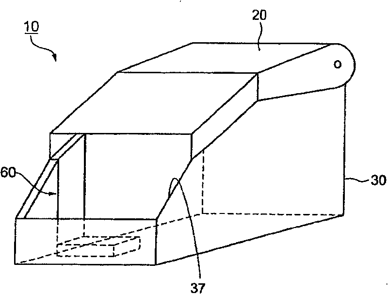
[0105] Such as figure 1 As shown, the casing 10 according to the first embodiment comprises a housing unit 30 having an opening 37 and capable of containing contents, a cover 20 connected thereto in an openable manner capable of at least partially covering the opening 37, and connecting the cover 20 and the case The body units 30 are mutually locked by the locking means 60 in the closed state. When locked after the cover 20 is closed, the locking device 60 confines the contents within the housing unit 30 . The locking device 60 is unlocked by an electric signal.

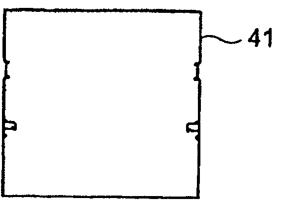
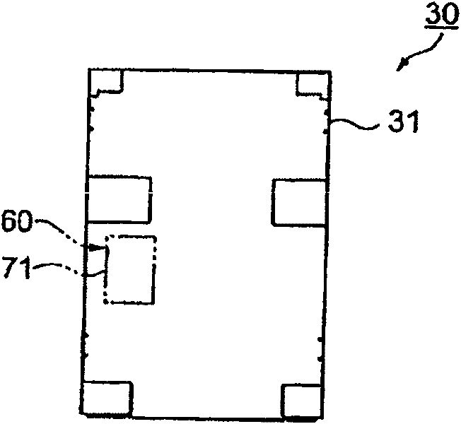
[0106] Such as Figures 2A to 2C As shown, the housing unit 30 includes a bottom panel 31 , a rear panel 41 and side panels 51 . The locking device 60 includes a locking member 61 and an electromagnetic actuator 71 operated by an electric signal. The locking part 61 is connected to the sid...


PUM


Abstract

To provide a printer with a locking mechanism which can prevent roll paper in a POS terminal and product sales registration equipment from being easily taken out from the outside.

Description

technical field [0001] The present invention relates to a locking device capable of preventing easy removal of parts inside a housing, and to the locking of printers used in POS (point of sale) terminals, electronic cash registers, etc., for printing receipts, tickets, vouchers of value, etc. device. Background technique [0002] In the related art, the value voucher includes prescribed characters or identification characters, such as a barcode printed on a specific paper. These valuable certificates, such as train tickets, entrance tickets and other securities do not necessarily need to be made in advance. Accordingly, characters can be printed out using a printing device (printer) or the like before the customer receives a service or is given a certificate of value. [0003] U.S. Patent No. 6,118,469 discloses a printer capable of printing specified items on receipt paper to generate sales slips or receipts for customers, to provide sales slips or receipts to customers w...

Claims


Application Information

Patent Timeline
Patent Type & Authority Patents(China)
IPC IPC(8): B41J29/00B41J3/00G07G1/00B41J29/08
Inventor 百濑勉小薮晃
Owner SEIKO EPSON CORP
Features
  • Generate Ideas
  • Intellectual Property
  • Life Sciences
  • Materials
  • Tech Scout
  • Unparalleled Data Quality
  • Higher Quality Content
  • 60% Fewer Hallucinations
Learn More