Horizontal deflection coil

A technology of horizontal deflection and deflection coil, which is used in the manufacture of magnetic deflection devices, cathode ray tube/electron beam tube, medical science, etc., and can solve the problems of not maintaining the shape of the wire portion 43, loss of convergence, and damage to product quality.

Inactive Publication Date: 2005-11-23
SAMSUNG ELECTRO MECHANICS CO LTD
View PDF0 Cites 0 Cited by
  • Summary
  • Abstract
  • Description
  • Claims
  • Application Information

AI Technical Summary

Problems solved by technology

Therefore, there is a defect that scattering occurs during the manufacturing process, whereby the shape of the wire portion 43 is not maintained, and variations are generated
[0035] In addition, due to the above drawbacks, the horizontal deflection coil 12 is suspended in the pressing direction (direction of the arrow), thereby causing the middle portion 12b of each product to have a different shape when the products are manufactured.
Therefore, there is a defect that in the two horizontal deflection yokes installed in the deflection yoke, the four intermediate portions have different shapes, thereby not generating the same deflection magnetic field, thus causing misconvergence due to scattering during the manufacturing process
In addition, there is also the fact that each product generates a different deflection magnetic field, thereby resulting in damage to product quality

Method used


Image

  • Horizontal deflection coil
  • Horizontal deflection coil
  • Horizontal deflection coil

Examples


Embodiment Construction

[0058] Reference will now be made to the preferred embodiments of the invention, examples of which are illustrated in the accompanying drawings.

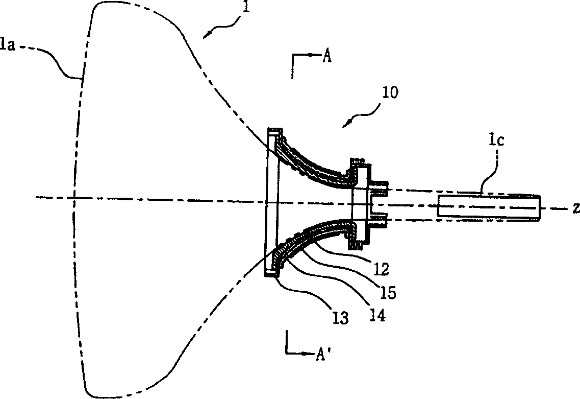
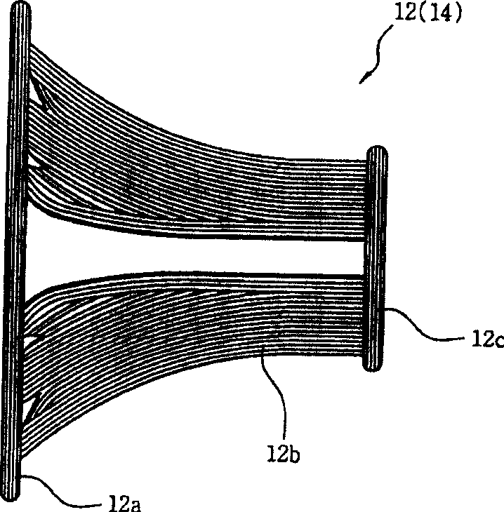
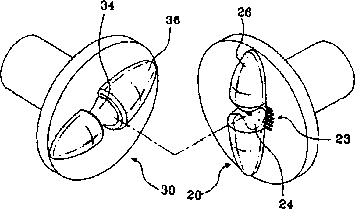
[0059] E.g, Figure 11 is a perspective view illustrating a horizontal deflection coil according to the present invention, Figure 12 is a side view illustrating a horizontal deflection coil wound by an upward support pin according to the invention, Figure 13 is a perspective view illustrating a mold for winding a deflection yoke winder according to the present invention, FIG. 14 is a perspective view illustrating a cylindrical pin and an upward support pin, and Figure 15 is a view illustrating a horizontal deflection coil mounted on a deflection yoke according to the present invention. For the convenience of description, in all the drawings, the same symbols are used to denote the same or similar components.

[0060] refer to Figure 11 , the horizontal deflection coil 100 includes a screen bending portion 12a, an intermediate ...


PUM

PropertyMeasurementUnit
angleaaaaaaaaaa

Abstract

Provided is a horizontal deflection coil of a deflection yoke in which the shape of the horizontal deflection coil is changed, thereby adjusting a screen wire distribution regardless of a middle wire distribution and constantly maintaining the shape of the middle portion of the horizontal deflection coil.

Description

technical field [0001] The present invention relates to a horizontal deflection coil applied to a deflection yoke, and more particularly, to changing the shape of the horizontal deflection coil to deflect the horizontal deflection coil of the yoke, thereby adjusting screen wire distribution, and Regardless of middle wire distribution. Background technique [0002] Typically, cathode ray tubes in televisions use electronic deflection technology. To irradiate electron beams, it is basically required to apply horizontal and vertical magnetic fields from the neck of the cathode ray tube. The two coils placed basically at a 90 degree angle to form these deflection magnetic fields are called "horizontal and vertical deflection yokes", and the combination of the deflection coils and ferrite core is called a "deflection yoke". [0003] The deflection yoke can be divided into three types, that is, a saddle type in which two deflection coils are designed with a saddle-shaped oblique...

Claims


Application Information

Patent Timeline
Patent Type & Authority Applications(China)
IPC IPC(8): H01J29/76H01J9/236H01J29/46H01J29/70
CPCH01J29/70H01J2229/7032H01J9/236A61F13/51104A61F13/472A61F2013/5127A61F2013/51147A61F2013/51186
Inventor 申东澈
Owner SAMSUNG ELECTRO MECHANICS CO LTD
Why Eureka
Try Eureka